Gprs wireless modem interface – Zilog EZ80F916 User Manual
Page 23
eZ80F91 Modular Development Kit
User Manual
UM017010-0112
GPRS Wireless Modem Interface
18
GPRS Wireless Modem Interface
The MDS Adapter Board includes connectors for adding a MultiTech
SocketModem GSM/GPRS data/fax wireless modem module, part num-
bers MTSMC-G-F1 (900/1800 MHz) or MTSMC-G-F2 (850/1900 MHz).
This interface is implemented on the UART1 (PCx) interface and consists
of connectors J3, J11, and J12. For information about the MultiTech mod-
ule, refer
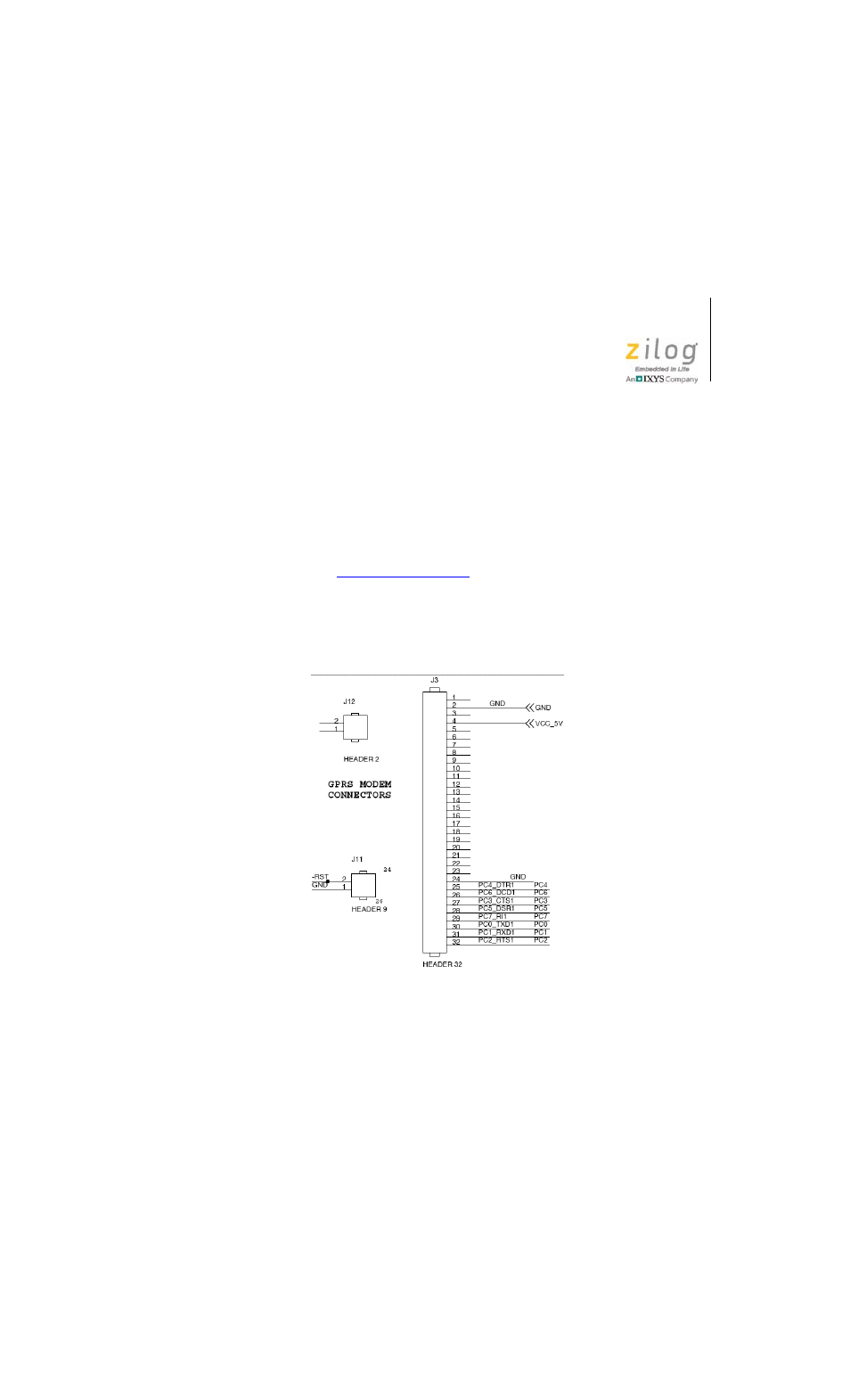
Figure 7 displays the pin layout of the three GPRS module connectors on
the eZ80Acclaim! MDS Adapter Board. Table 5 lists connector J3 pins
and functions. Table 6 lists connector J11 pins and functions.
Figure 7. eZ80Acclaim! MDS Adapter Board GPRS
Wireless Modem Connectors J3, J11 and J12
This manual is related to the following products: