I/o mini-module connector j2, Table 2, per – Zilog EZ80F916 User Manual
Page 14
eZ80F91 Modular Development Kit
User Manual
UM017010-0112
eZ80F91 Module Interface
9
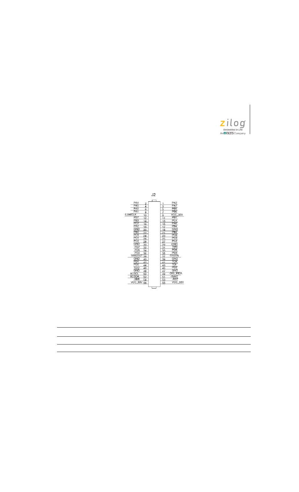
I/O Mini-Module Connector J2
Figure 4 displays the pin layout of the 56-pin Peripheral Bus Mini-Mod-
ule Connector, J2, on the eZ80Acclaim! MDS Adapter Board. Table 2
lists the pins and their functions.
Figure 4. eZ80Acclaim! MDS Adapter Board I/O Mini-Module Connector J2
Table 2. eZ80Acclaim! MDS Adapter Board I/O
Mini-Module Connector J2 Identification
1
Pin
Symbol
Signal Direction
Active Level
eZ80F91 Signal
2
1
PA3
Bidirectional
n/a
Yes
2
PA4
Bidirectional
n/a
Yes
Notes:
1. To simplify interface description, Power and Ground nets are omitted from this table. The entire interface is
represented in the eZ80Acclaim! MDS Adapter Board schematics; see Figures 8 and 9.
2. The Power and Ground nets are connected directly to the eZ80F91 device.