Nudc-4u panel functions overview – Xtramus NuDC-4U V2.1 User Manual
Page 7
7
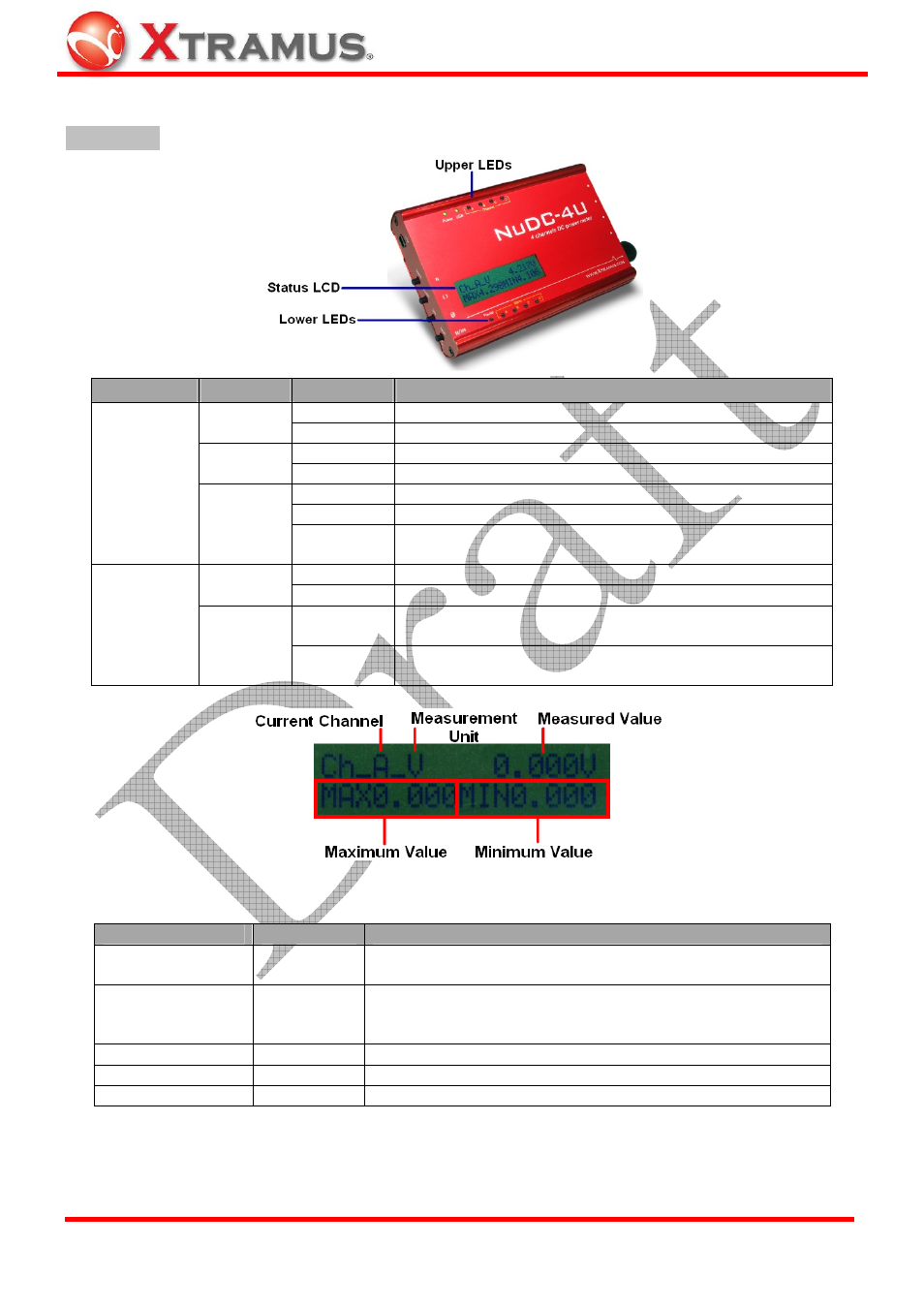
1.3. NuDC-4U Panel Functions Overview
Front Panel
LEDs
Label
Status
Description
ON
NuDC-4U is power on and ready for tests
Power
OFF
NuDC-4U is power off
ON
NuDC-4U is connected to PC via USB cable
USB
OFF
NuDC-4U is NOT connected to PC via USB cable
Yellow
Channel A/B/C/D is connected to a power-on DUT
Green
Channel A/B/C/D is connected to a power-off DUT
Upper LEDs
Channel
A ~ D
Blinking
Green
Channel A/B/C/D is connected to a power-off DUT, and
Power Status of channel A/B/C/D are displayed on LCD
ON
Pausing current Power Status readings displayed on LCD
Pause
OFF
Power Status readings is displaying on LCD in real-time
ON
Current power status of channel A/B/C/D exceeds pre-set
alarm criteria
Lower LEDs
Alarm
A ~ D
OFF
Current power status of channel A/B/C/D is under pre-set
alarm criteria, or no alarm criteria is not configured
NuDC-4U is embedded with a 2x16 characters LCD for displaying NuDC-4U system and power status.
Item
Mark
Description
Current Channel
Ch_X
Show power status of current channel. "X" represents the 4
channels of NuDC-4U: A, B, C, and D
Measurement Unit
-V / -I / -W
Unit of power status:
¾
V:
Voltage
¾
I:
Ampere
¾
W:
Watt
Measured Value
Current value in Volt, Ampere or Watt
Maximum Value
MAX
Maximum value during the test period
Minimum Value
MIN
Minimum value during the test period
E-mail: [email protected]
Website: www.Xtramus.com
XTRAMUS TECHNOLOGIES
®