Vectronics VEC-101K User Manual
Page 13
VEC-101K Owner's Manual
Shortwave Converter Kit
11
! ! 8. C7
.1-uF monolithic (.1 or 104)
Locate the two 47-pF monolithic capacitors (47 or 470). Do not use the 47-pF
disc ceramic at this point! Install and solder at the following locations:
! ! 9. C8
47-pF monolithic (47 or 470)
! ! 10. C9
47-pF monolithic (47 or 470)
! ! 11. Locate the 47-pF (47 or 470) ceramic disc capacitor. Install and
solder at location C3.
Locate the two 12-pF monolithic capacitors (12 or 120). Install and solder at the
following locations:
! ! 12. C1
12-pF monolithic (12 or 120)
! ! 13. C2
12-pF monolithic (12 or 120)
Phase 3: Jumpers/IC Sockets and Chips
Select a scrap capacitor lead end for use as a jumper wire, as shown below. Use
needle-nose pliers to form to fit, making sure the jumper lies flat on the PC
board when installed:
span
discarded lead end
! ! 1. Prepare, install, and solder a jumper wire at JMP2.
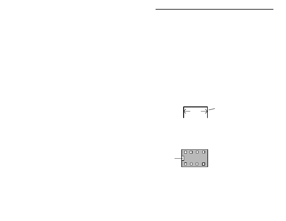
Locate the 8-pin DIP integrated IC socket. Note that the socket is “keyed”, and
should be installed with its key aligned to the silk-screened outline on the PC
board.
1 2 3 4
8 7 6 5
Installation
Key
Pin Numbers
Top view of socket
! ! 2. Install and solder the 8-pin IC socket at location U1. Observe proper
orientation!