Internal connectors and dip switch settings, Vga connector, Flash/debug connector – NEXCOM VMC 100 User Manual
Page 37: Vga connector flash/debug connector
Copyright © 2014 NEXCOM International Co., Ltd. All rights reserved
23
VMC 100/1100 Series User Manual
Chapter 3: Jumpers and Connectors
Internal Connectors and DIP Switch Settings
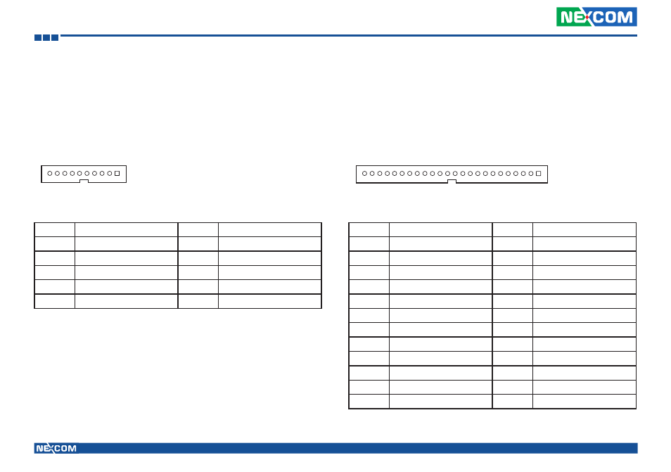
Pin
Definition
Pin
Definition
1
VGA_+5V
2
VGA_CLK
3
VGA_DATA
4
VGA_VS
5
VGA_HS
6
GND
7
VGA_BLUE
8
VGA_GREEN
9
VGA_RED
10
GND
VGA Connector
Connector size: 1x10 10-pin header, 1.0mm pitch
Connector location: J2
10
1
24
1
Flash/Debug Connector
Connector size: 1x24 24-pin wafer, 1.0mm pitch
Connector location: J1
Pin
Definition
Pin
Definition
1
GND
2
GND
3
EC_KSI5
4
EC_KSI4
5
EC_KSI3
6
EC_KSI2
7
EC_KSI1
8
EC_KSI0
9
GND
10
GND
11
GND
12
GND
13
GND
14
EC_KSO10
15
EC_KSO9
16
EC_KSO8
17
EC_KSO7
18
EC_KSO6
19
EC_KSO5
20
EC_KSO4
21
EC_KSO3
22
EC_KSO2
23
EC_KSO1
24
EC_KSO0
This manual is related to the following products: