NEXCOM VTC 1000 User Manual
Page 69
Copyright © 2011 NEXCOM International Co., Ltd. All rights reserved
56
VTC 1000 User Manual
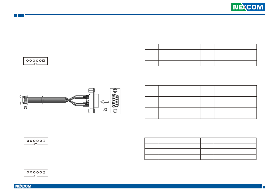
Appendix E: Pin Definition for GPS with Dead Reckoning Feature
VIOB-GPS-DR01 consists of S2532DR and cables.
Here are the connector and cable pin definition for VIOB-GPS-DR01.
Pin
Definition
Pin
Definition
1
GND
4
GPIO22
2
DIRECTION
5
1PPS
3
ODOMETER
6
GND
Pin
Definition
Pin
Definition
1
1PPS
6
GND
2
GPIO22
7
NC
3
NC
8
NC
4
ODOMETER
9
GND
5
DIRECTION
Connector pin definition of P2
Connector pin definition of P1
(2) Connect VIOB-GPS-DR01 and VTC 1000 CPU Board with Cable
(On VIOB-GPS-DR01)
1
1
6
6
(On VTC 1000 CPU Board)
A. Connector type: 1x6 6-pin header
B. Connector location: J1
A. Connector type: 1x6 6-pin header
B. Connector location: J2
Pin
Definition
Pin
Definition
1
+V3.3S
4
SP_TX1
2
GND
5
GPS_LED#
3
SP_RX1
6
GPS_BAT
Connector pin definition of J1
C. GPS module to DB9 Cable (6P TO D-SUB-9M)
1
6
(1) Connect VIOB-GPS-DR01 and DB9 Cable
(On VIOB-GPS-DR01)
A. Connector type: 1x6 6-pin header
B. Connector location: J1
Note: In order to fix the additional DB9 connector, increasing the height
of enclosure is necessary.