Lnb specifications – KBC Networks MiniLink User Manual
Page 10
MINILINK® 5.8 LNB DESCRIPTION, OPERATION & SPECIFICATIONS
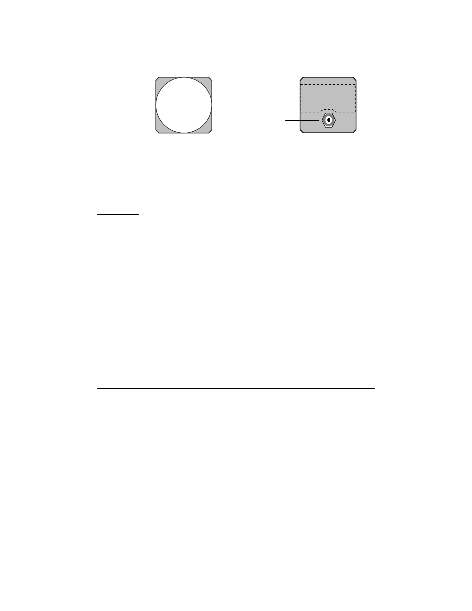
A. FRONT VIEW
B. REAR VIEW
1. RF OUTPUT
Coaxial cable output to the receiver (971 – 1088 MHz). Power supplied to the LNB from receiver
through this cable at 9-16 VDC.
IMPORTANT:
Use only RG 6 coaxial cable with the supplied waterproof “F” connectors to
connect Receiver and LNB. Cable lengths should be a minimum of 10 feet and a maximum of
100 feet.
WARNING: MAKE ALL COAX CONNECTIONS WHILE THE RECEIVER IS
POWERED DOWN. CONNECTIONS MADE WHILE THE RECEIVER IS ON COULD
CAUSE DAMAGE TO THE UNIT.
LNB OPERATION
A. LOCATION / MOUNTING
Since the LNB is weatherproof, it can be wall or pole mounted using the equipment supplied with
environmental systems only. (MiniLink 5.8 model numbers with an “E” at the end are environmental
systems.) Contact KBC if you do not have wall/pole mounting hardware.
B. MAINTENANCE
Your KBC product is an example of superior design and craftsmanship. Use the system only
within the environmental specifications indicated. High temperatures can shorten the life of
electronic devices and melt plastic parts. Excessive mechanical shock can damage the case,
connectors or internal circuit board. Use the supplied weatherproof F-Connectors and crimp onto
the Quad-shielded RG 6 coaxial cable to ensure weatherproof mounting.
LNB SPECIFICATIONS
RF SECTION
LO
Frequency
4770
MHz
IF
Output 971
to
1088
MHz
MECHANICAL
Dimensions
2.75” x 2.75” x 1.5”
Weight
7.7
oz
Connections
Waterproof
“F”
connectors (2 included with system)
Cable (see note below)
RG 6 Quad-shield Coaxial Cable
(10
ft
minimum,
100
ft
maximum)
POWER
Power Requirements
9-16 VDC @ 220 mA
(LNB
power
supplied
by
Receiver)
ENVIRONMENTAL
Humidity 100%
non-condensing
Operating Temperature
-20F to +180F
*For product improvement, design and specifications are subject to change without notice.
- 8 -
1