Sheet4, Drawing view5, Detail view a (1 : 5) – Future Automation MLS User Manual
Page 4: Drawing view38, Drawing view39, Detail view b (1 : 5), Future automation mls, Stage 2, Marine lift swivel mechanism instruction sheet
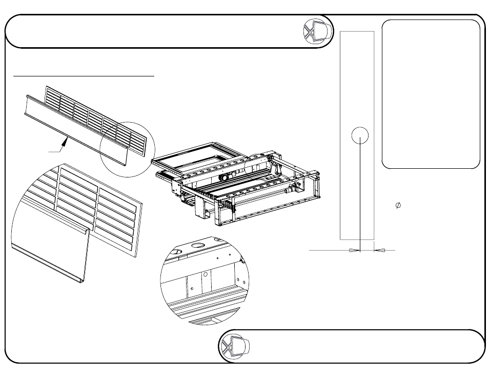
A
VIEWING SIDE
Aluminium
Flap
DETAIL A
SCALE 1 : 5
Take care when fixing the surfaces together.
Place the objects on a flat surface to make
sure the edges are properly alligned
when they come into contact.
Try to use as many self adhesive pads
as possible to get the most secure fixture.
72.50
B
DETAIL B
SCALE 1 : 5
Stage 2
Fitting flap and base to mechansim
FIXING
Firstly, before attempting
to fix the base panel to
the mechanism, it will
be necessary to
remove the mounting
frame, for ease of
working.
Make sure the base panel
lines up squarely, directly
on top of the lifting beam.
Always consult
ML TECHNICAL SHEET
before fabricating any
flaps or base panels.
1 large hole to be
drilled in base panel.
This hole should be
86mm to allow for
adjustment later.
The hole's centre has
to be 72.5mm away
from the back edge
of the base panel.
The surfaces of the flap should ideally be varnished
or painted to help prevent it from warping.
Remove the screen mount from the mechanism and put the
base on the beam. With the base panel on the beam, it will
be possible to mark where the wood screws will need to go
through the support plates into the base panel. Mark
where the holes need to go and then drill a pilot
hole for the screws. Then screw in the
provided wood screws with washers.
The 6mm flap and the base should
be made as part of the cabinet.
Sheet 3 of 18
ISSUE: 011
www.futureautomation.co.uk
FUTUREAUTOMATION
MLS
Marine Lift Swivel Mechanism
Instruction Sheet