Rear panel, Cuenet (lan), F.d. button – CUE controlCUE User Manual
Page 9: Audio line, Control ports, Pwr in 24 vdc, Controlcue-one, Controlcue-two
9
controlCUE Controllers | Rear Panel
© CUE, a.s. | All Rights Reserved.
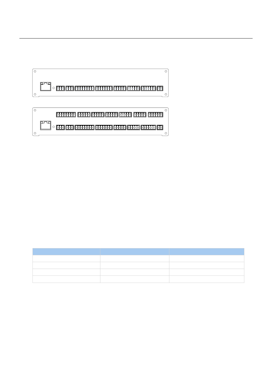
Rear Panel
This chapter describes rear panel equipped with all connectors. For more details about connection see
chapter Connecting.
CUEnet (LAN)
The 10/100 BaseT LAN is a standard network connection using RJ-45 connector. For more details see chapter
Connection.
Yellow indicator - network activity
Green indicator - network link
F.D. Button
When pressed the system default function is performed. For system default values see chapter Factory Default
and System Default. A thin screwdriver is needed for press of this button.
AUDIO LINE
Two 3-pin connectors provide unbalanced audio line input (IN) and output (OUT).
Control Ports
Rear panel of controlCUE is equipped with following control ports
Port
controlCUE-one
controlCUE-two
Serial port RS-232/422/485
2
6
IR/Serial output
4
8
General I/O
4
8
Relays 24 V, NO-C-NC contacts
2
4
PWR IN 24 VDC
Powering of controlCUE is provided by 24 VDC. Use only delivered power supply.
L G R
L G R
S G S G S G S G
+ G 1 2 3 4 5
1 2 3 4 5
S S S S G
NC C NO
NC C NO
+ G
PWR IN
RELAY
GENERAL I/O
SERIAL
IR/SERIAL
AUDIO LINE
CUEnet (LAN)
default IP address
192.168.1.127
IN
OUT
1
2
3
4
1
2
1 2 3 4 G
1
2
24 VDC
F. D.
controlCUE-one
CUEnet (LAN)
default IP address
192.168.1.127
L G R
L G R
S G S G S G S G
+ G 1 2 3 4 5
1 2 3 4 5
S S S S G
NC C NO
NC C NO
+ G
PWR IN
RELAY
SERIAL
IR/SERIAL
AUDIO LINE
IN
OUT
1
2
3
4
1
2
GENERAL I/O
1 2 3 4 G
1
2
24 VDC
F. D.
1 2 3 4 5
1 2 3 4 5
S S S S G
NC C NO
NC C NO
1 2 3 4 5
S G S G S G S G
SERIAL
3
4
5
6
RELAY
3
4
IR/SERIAL
5
6
7
8
GENERAL I/O
5 6 7 8 G
1 2 3 4 5
controlCUE-two