Front panel, Pwr indicator, Link indicator – CUE controlCUE User Manual
Page 7: Cpu indicator, Ir sensor, Serial port indicator, Ir/serial output indicator
7
controlCUE Controllers | Front Panel
© CUE, a.s. | All Rights Reserved.
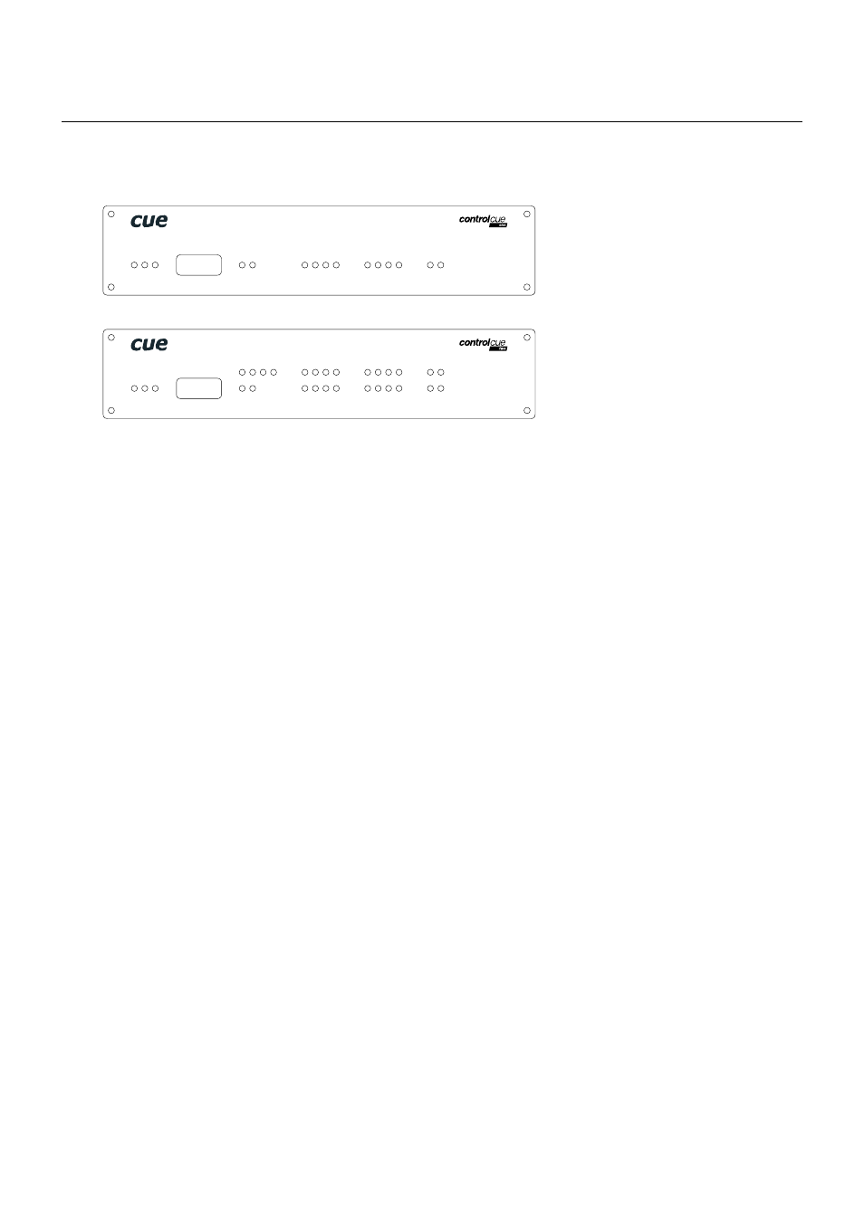
Front Panel
This chapter describes front panel equipped with indicators and IR sensors.
PWR Indicator
Off
No power presented.
Blue On
Power 24 V is presented. The unit is ready.
LINK Indicator
Off
Network is not detected.
Green On
Network detected.
CPU Indicator
This Green LED indicates
▪ The end of the operating system boot up by flashing OK in Morse code. Operating system is booted
after the unit has either been reset or switched on. The booting time is approx. 15 seconds.
▪ Capture ready during IR capture.
IR SENSOR
The window marked by IR SENSOR covers two IR sensors and one LED indication.
1. The built-in IR sensor carries the same functionality as irCUE Receiver or irCUE Receiver 485. This
means that controlCUE can receive IR signal from CUE wireless IR control panels without the need to use
any external IR receiver.
2. The second built-in IR sensor allows IR codes capture. The yellow LED indicates the received infra-red
signal is ok and it helps to set optimum distance between the receiver and captured IR remoter.
SERIAL Port Indicator
Off
No data transmitted or received through the serial port.
Green On or Flashing
Data is being transmitted through the serial port.
Red On or Flashing
Data is being received through the serial port.
IR/SERIAL Output Indicator
Off
No data or IR code transmitted through the IR/serial port.
Yellow On or Flashing
Data or IR code is being transmitted through the IR/serial port.
1
2
1
2
3
4
1
2
1
2
3
4
SERIAL
IR/SERIAL
GENERAL I/O
RELAY
IR SENSOR
PWR LINK CPU
controlCUE-one
1
2
1
2
1
2
3
4
IR/SERIAL
1
2
3
4
GENERAL I/O
RELAY
IR SENSOR
PWR LINK CPU
3
4
5
6
SERIAL
5
6
7
8
5
6
7
8
3
4
controlCUE-two