13 appendix, Appendix, Appendix, chapter 13) – Crompton Controls DCM User Manual
Page 62
Emotron AB 01-2120-01r2
Appendix
61
13
Appendix
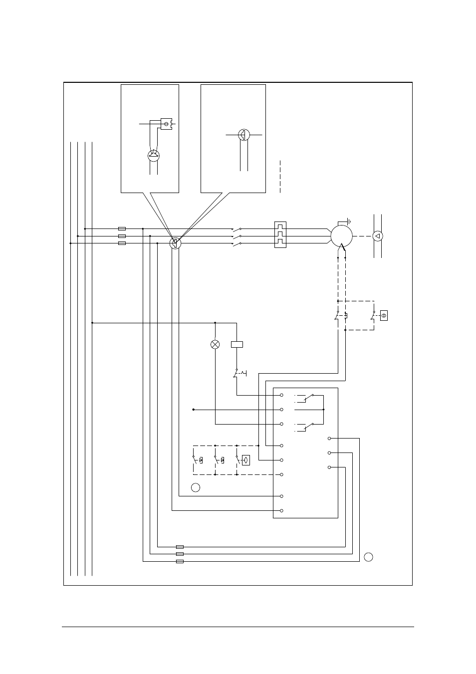
Fig. 18 Single-pump system installation example (Figur 13)
L1
L2
L3
N
Th
e
rm
o
-
co
nt
a
c
t
S1
S2
Dig
S
GND
Te
mp
P
u
mp
C
Allarm
L3
L2
L1
CTM xxx
L1
Number of primar
y and sec
o
ndar
y windings see
Ta
ble 2
Number of primar
y windings see
Ta
ble 1
Alt
e
rnativ anslutning
Ex
ce
eding 100 Amps
Upt
o
100 Amp
SS
L1
Standar
d
tr
ansf
ormer
CTM 010
DCM
A
A
S
elec
tion,
see M
a
nual:
Digital Input c
o
nnec
tion
Dig and SGND
, t
e
rm.
3 and 4.
K1
F1
U
V
W
M
Au
to
se
t
Reset
High lev
e
l
K1
Alar
m
1
2
3
4
5
6
7
8
9
11
13
M
a
x 240V
A
C
T
h
ermist
or PT
C
-
+
F1
Stop
M
a
x.
10 A