Alarm codes connector diagrams, Applied motion products, inc, Alarm codes – Applied Motion BLuDC4-Q User Manual
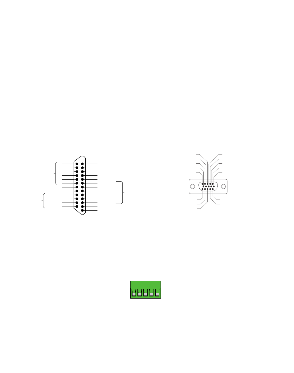
Page 32: Connector diagrams, Db-25 i/o connector hd-15 encoder connector
Alarm Codes
In the event of an error, the green LED on the main board will flash one or two times, followed by a series of red flashes. The
pattern repeats until the alarm is cleared.
Code
Code
Code
Code
Code
Error
Error
Error
Error
Error
1 red, 1 green
position error exceeds fault limit
2 red, 1 green
ccw limit
2 red, 2 green
cw limit
3 red, 1 green
drive internal temperature exceeds 85°C
3 red, 2 green
motor over temperature
4 red, 1 green
power supply voltage is more than 55 VDC
4 red, 2 green
power supply voltage is less than 18 VDC
5 red, 1 green
over current / short circuit
6 red, 1 green
bad commutation(Hall) signal
6 red, 2 green
bad encoder signal
7 red, 1 green
serial communication error
Connector Diagrams
Applied Motion Products, Inc.
404 Westridge Drive Watsonville, CA 95076
Tel (831) 761-6555 (800) 525-1609 Fax (831) 761-6544
www.appliedmotionproducts.com
1/30/06
X COMMON
X7/CW Limit
X6/CCW Limit
X3/Servo Enable
X5
X4/Alarm Reset
Analog IN-
Analog IN+
X2/DIR-
X2/DIR+
X1/STEP/PWM+
X1/STEP/PWM-
GND
Z-
Z+
B-
B+
A-
A+
Front View
21
22
23
24
25
13
12
11
10
9
8
7
6
5
4
2
3
1
20
19
18
17
16
15
14
Shared
Common
Shared
Common
Y1/BRAKE
Y2/INPOSN
Y3/ALARM
Y COMMON
+5V OUT (200 mA MAX)
GND
Encoder
Outputs
RX+
RX
–
TX
–
TX+
GND
RS-485/422
ENCODER
(ALL
ENCODER
(ALL
ENCODER
(ALL
(ALL
MOTOR
&RONT
DB-25 I/O Connector
HD-15 Encoder Connector