Connecting input signals – Applied Motion BLuDC4-Q User Manual
Page 14
14
14
14
14
14
BLuDC-S,-Q Hardware manual
BLuDC-S,-Q Hardware manual
BLuDC-S,-Q Hardware manual
BLuDC-S,-Q Hardware manual
BLuDC-S,-Q Hardware manual
Connecting Input Signals
The BLU servo drives have four types of inputs:
• high speed digital inputs for step & direction commands or encoder following, 5 volt logic
• digital inputs for other signals, 12 - 24 volt logic
• analog input for torque and speed commands
BLU-Q and BLU-S Inputs
These drives include seven digital inputs and one analog input.
CW & CCW Limit: can be used to inhibit motion in a given direction, forcing the motor and load to
travel within mechanical limits. Can be configured for active closed, active open or not used.
STEP & DIR: digital signal commanding position. Quadrature signals from encoders can also be
used.
Servo Enable: activates servo. Can be configured for active closed, active open or not used.
Alarm Reset: Activate this signal momentarily to reset a drive fault or alarm. Can be configured for
active closed, active open or not used.
Analog In: analog torque, velocity or position command signal. Can be configured for 0-10V, 0-
5V, ±10V or ±5V, with or without offset.
BLU-SE & -QE Inputs
These drives include eight additional programmable inputs on screw terminal connectors.
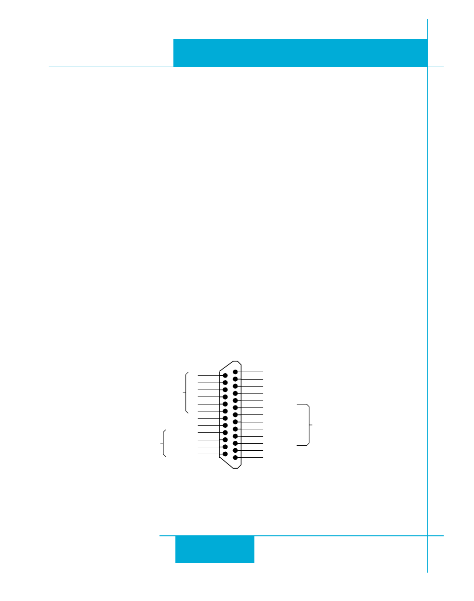
Connector Pin Diagrams
DB-25 Connector
Available on all drives
X COMMON
X7/CW Limit
X6/CCW Limit
X3/Servo Enable
X5
X4/Alarm Reset
Analog IN-
Analog IN+
X2/DIR-
X2/DIR+
X1/STEP/PWM+
X1/STEP/PWM-
GND
Z-
Z+
B-
B+
A-
A+
Front View
21
22
23
24
25
13
12
11
10
9
8
7
6
5
4
2
3
1
20
19
18
17
16
15
14
Shared
Common
Shared
Common
Y1/BRAKE
Y2/INPOSN
Y3/ALARM
Y COMMON
+5V OUT (200 mA MAX)
GND
Encoder
Outputs