Programmable outputs, Sinking output – Applied Motion BLuDC4-Q User Manual
Page 23
23
23
23
23
23
BLuDC-S,-Q Hardware manual
BLuDC-S,-Q Hardware manual
BLuDC-S,-Q Hardware manual
BLuDC-S,-Q Hardware manual
BLuDC-S,-Q Hardware manual
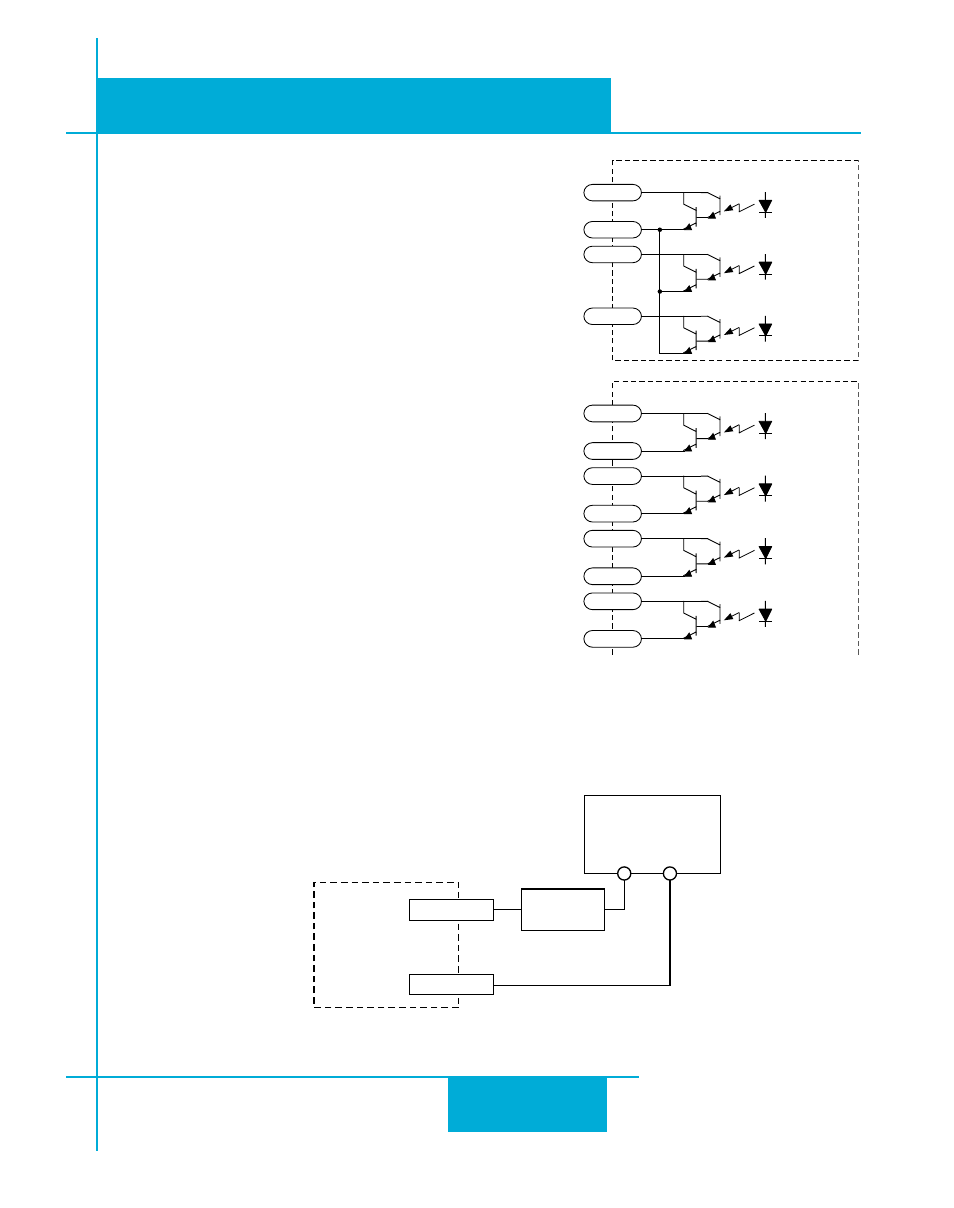
Programmable Outputs
The BLU-S and BLU-Q drives feature three digital outputs:
Brake
Brake
Brake
Brake
Brake: controls an electric brake relay, automatically releas-
ing and engaging as the drive requires
Alarm
Alarm
Alarm
Alarm
Alarm: closes or opens when a drive fault or alarm condi-
tion occurs. The red and green LEDs will flash an error
code.
In Position
In Position
In Position
In Position
In Position: indicates that the drive has achieved a desired
goal, such as a target position.
The -SE and -QE have four additional programmable out-
puts.
The outputs can be used to drive LEDs, relays and the inputs
of other electronic devices like PLCs and counters. For
OUT1-4, the “+” (collector) and “-” (emitter) terminals of
each transistor are available at the connector. This allows
you to configure each output for current sourcing or sinking.
The BRAKE, ALARM and INPOSN outputs can only sink
current. The COM terminal must be tied to power supply (-).
Diagrams of each type of connection follow.
Do not connect the outputs to more than 30VDC.
The current through each output terminal must not exceed 100 mA.
Sinking Output
inside BLU Servo
BRAKE
COM
ALARM
INPOSN
14
17
15
16
-SE & -QE only
OUT1+
OUT1-
OUT2+
OUT2-
OUT3+
OUT3-
OUT4+
OUT4-
BLU Servo
OUT-
OUT+
5-24 VDC
Power Supply
+
–
Load