2 connecting the tsm17c communications, Tsm17c hardware manual, Txd rxd can_h can_l gnd – Applied Motion TSM17C-1CG User Manual
Page 13
13
Rev. A
920-0085
TSM17C Hardware Manual
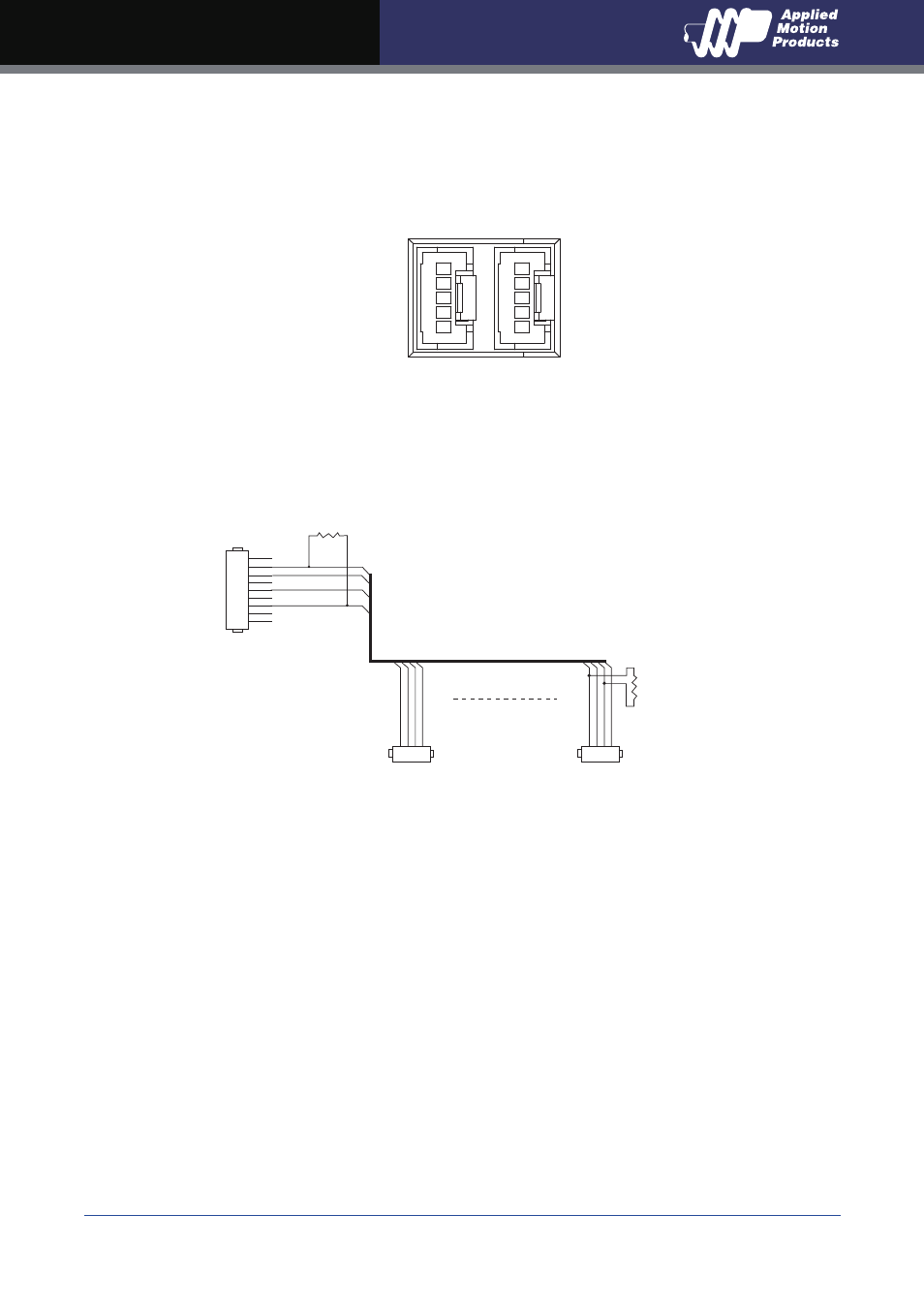
3.2 Connecting the TSM17C Communications
Two standard 5-pin disconnectable crimp style connectors are used for the communications
interface of TSM17C, and both of them can be used for RS-232 serial interface and CANopen
daisy-chain by different cable included with TSM17C.
CANopen Connector Diagram
The TSM17C is configured using a combination of rotary switches and an RS-232 serial link,
and then may be deployed on a distributed CANopen network. The RS-232 interface is used for
configuration, tuning, node ID setting and Q program downloading. The CANopen network should
be connected in a daisy-chain fashion, with a 120 ohm terminating resistor at each end of network.
Locate the TSM17C within 1.5 meters of the PC. Plug the DB9 connector of the communication
cable that came with the drive into the serial port of the PC. Plug the 5-pin crimp style connector
into one of the two appropriate connector on the TSM17C. Secure the cable to the PC with the
screws on the DB9 connector.
Note: If the PC does not have an RS-232 serial port, a USB Serial Converter will be needed.
You can contact Applied Motion Products to buy a USB to RS-232 converter.
The RS-232 circuitry does not have any extra electrical “hardening” and care should be taken
when connecting to the RS-232 port as hot plugging could result in circuit failure.
TXD
RXD
CAN_H
CAN_L
GND
1
.1” Spacing Spring Plug
DSUB9 Female
R termination:
Network must be terminated at each
end with a 120 ohm resistor.
n:
Cable may be made with up to 127 drive
connectors. Termination is only required
at each end.
.1” Spacing Spring Plug
n*
R termination*
120 ohm nominal
R termination*
120 ohm nominal
1
CAN_L
CAN_L
CAN_GND
CAN_GND
CAN_BUS
CAN_SHLD
CAN_SHLD
CAN_H
CAN_H
2
3
4
2
3
4
5
6
7
8
9
1
CAN_L CAN_GND
CAN_SHLD
CAN_H
2
3
4