Step 4: load inertia, Step 5: step size, 20 str4/8 hardware manual – Applied Motion STR4 User Manual
Page 20
20
STR4/8 Hardware Manual
920-0030J
5/12/2015
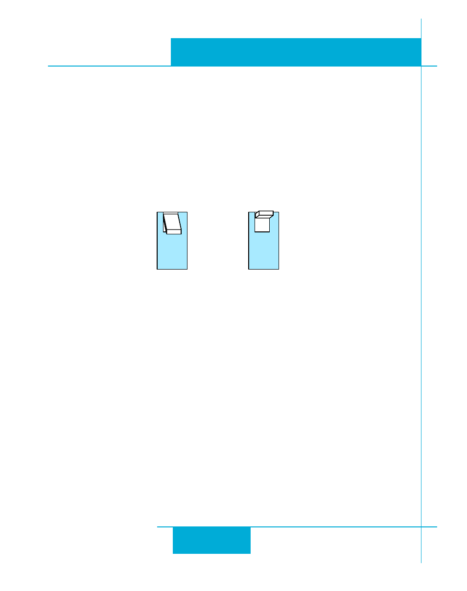
Step 4: Load Inertia
The STR drives include anti-resonance and electronic damping features which greatly improve
motor performance. To perform optimally, the drive must understand the electromechanical
characteristics of the motor and load. Most of this is done automatically when you select the
motor by setting the rotary switch. To further enhance performance, you must set a switch to
indicate the approximate inertia ratio of the load and motor. The ranges are 0 to 4X and 5 to
10X. The motors table shown in Step 1 of this section include the rotor inertia of each motor.
Please divide the load inertia by the rotor inertia to determine the ratio, then set switch 3 ac-
cordingly, as shown. For assistance in calculating the load inertia of your application contact our
Applications department.
Step 5: Step Size
The STR requires a source of step pulses to command motion. This may be a PLC, an indexer, a
motion controller or another type of device. The only requirement is that the device be able
to produce step pulses whose frequency is in proportion to the desired motor speed, and be
able to smoothly ramp the step speed up and down to produce smooth motor acceleration
and deceleration.
Smaller step sizes result in smoother motion and more precise speed, but also require a higher
step pulse frequency to achieve maximum speed. The smallest step size of the STR drives is
1/20,000th of a motor turn. To command a motor speed of 50 revolutions per second (3000
rpm) the step pulses frequency must be 50 x 20,000 = 1 MHz. Many motion devices, especially
PLCs cannot provide step pulses at such a high speed. If so, the drive must be set for a lower
number of steps per revolution. Six different settings are provided in the STR drive, as shown
in the table on the next page.
Please choose the one that best matches the capability of your system.
3
5-10X
3
0-4X