Installation – ABUS Technologies Log Box-AA Data Logger User Manual
Page 9
ABUS TECHNOLOGIES INC.
9
Log Box-AA
4.5 Digital Input (DI)
The Digital Input that can be used to guide the logger readings is available in terminals 7 (-) and
10 (+) of CN2.
5. INSTALLATION
5.1 Recommendation
1. Signal wires should be installed in grounded conduits and away from power or contactor wires.
2. Instruments must be powered only by an exclusive power supply.
3. System failure should always be taken into account when designing a control panel to avoid
irreversible damage to equipment or people.
4. Installing RC filters (47R and 100nF, serial) is strongly recommended at contactor coils or any other
inductors.
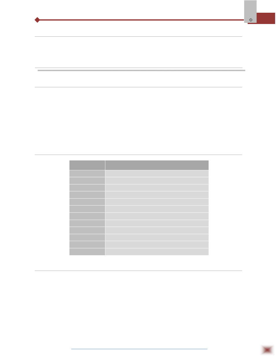
5.2 Input Signal
5.3 Panel
The Status Indicators are located in the logger front panel. They indicate the current working
conditions of the unit.
LOG Indicator (Logging): While in stand-by (not logging) or after a series of acquisitions is ended, it
flashes once at every four seconds. During login it flashes twice at every
four seconds.
TYPE
CHARACTERISTICS
J
Range: -50 to 760 °C (-58 to 1400ºF)
K
Range: -90 to 1370 °C (-130 to 2498ºF)
T
Range: -100 to 400 °C (-148 to 752ºF)
N
Range: -90 to 1300 °C (-130 to 2372ºF)
R
Range: 0 to 1760 °C (32 to 3200ºF)
S
Range: 0 to 1760 °C (32 to 3200ºF)
B
Range: 150 to 1820 °C (32 to 3308ºF)
Pt100
Range: -200.0 to 650.0 °C (-328 to 1202ºF)
0-50mV
Linear. Programmable range of -32768 to 32767
4-20 mA
Linear. Programmable range of -32768 to 32767
0-20 mA
Linear. Programmable range of -32768 to 32767
0-10Vdc
Linear. Programmable range of -32768 to 32767