ABUS Technologies Log Box-AA Data Logger User Manual
Page 18
ABUS TECHNOLOGIES INC.
18
Log Box-AA
Channel 1: Opens the Input 1 Settings screen.
Tag: Defines a name for Channel 1.
Input: Informs the input type used in Channel 1:
Unit: Defines the unit of the variable. For 0-20mA, 4-20mA, 0-50mV and 0-10V
the user should write the required unit.
Logging Mode: It defines how the value measured will be logged. Options are:
Instantaneous: One reading and one logging at each reading “Interval”;
Average: Ten readings at each reading interval. The average value of readings
is the value recorded;
Minimum: Ten readings at each reading interval. The lowest value found is
recorded;
Maximum: Ten readings at each reading interval. The highest value found is
recorded;
Lower/Upper Range Value: Allows the user to define the reading range for the
0-20mA, 4-20mA, 0-50mV and 0-10V inputs.
Offset: This parameter is used to correct small known mistakes the input signal
may present, such as during sensor switching, transmitter replacement, etc.
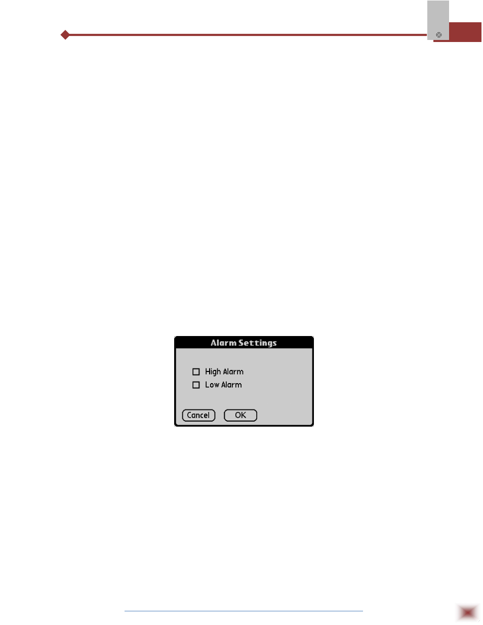
Alarms: Enables an alarm that is triggered according to user-defined
parameters.
Alarm settings screen
Cancel and OK buttons cancel and save configurations defined in Channel 2 screen.
Channel 2:
Has the same parameters as described for Channel 1.
Clocks:
Provides access to Logger and Palm clocks. When a new configuration is sent
to the logger, clocks are updated.
Battery:
Defines the moment when the logger turns on the battery switch, before each
reading is performed. Time (up to 10 seconds) can not exceed the mean time
between measurements.
After configuring clocks, click Apply to send this configuration to the Logger, returning to the
Monitoring screen.