Cofiguration – ABUS Technologies A1500 Universal Process Indicator User Manual
Page 9
ABUS TECHNOLOGIES INC.
9
A1500
non alarm condition followed by a new occurrence for the alarm. The initial blocking is disabled for the
sensor break alarm function.
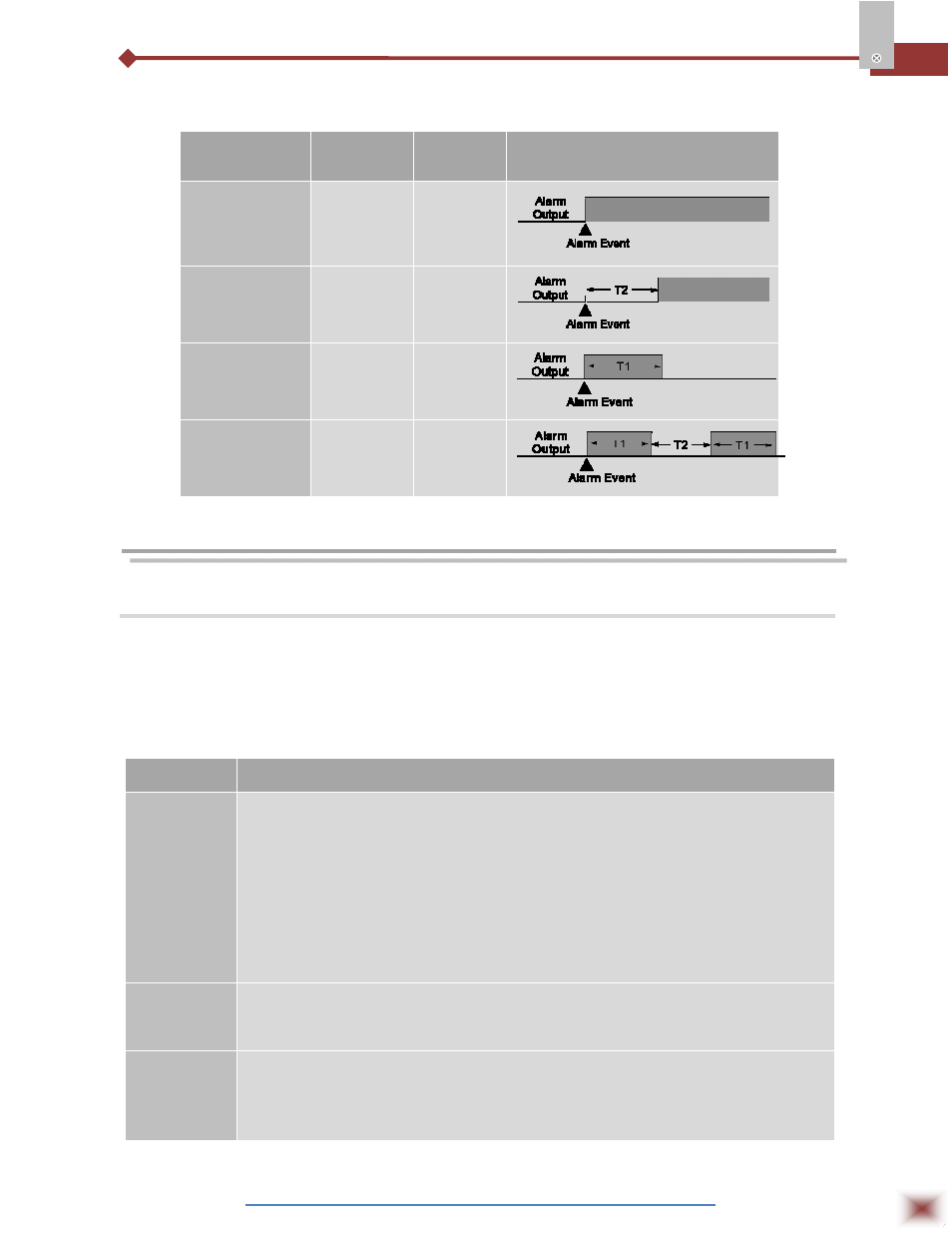
ADVANCED
FUNCTION
T1
T2
ACTION
Normal
Operation
0
0
Delayed
0
1s to 6500s
Pulse
1s to 6500s
0
Oscillator
1s to 6500s
1s to 6500s
7. COFIGURATION
7.1 Programming the Indicator
7.1.1 Work Cycle
This is the first cycle. At power up the indicator will display the Process Variable (PV). The
alarm triggering points are also displayed at this cycle (alarm Set-points). To run through this cycle just
press the P key.
PARAMETERS
PROMPT PARAMETER DESCRIPTION
8.8.8.8.8.
Measure. Shows the measured variable. For Pt100 or thermocouples the display will
show the absolute temperature value.
For 4-20mA, 0-50mV, 0-5V and 0-10mV inputs the display shows the values defined
in the”in.LoL” and “in.kiL” prompts.
With the hold function programmed the display shows the frozen variable and
alternates with the message “koLd”.
Likewise, with Peak Hold function programmed the high limit is displayed with the
“P.koLd” prompt alternately.
Should any fault situation occur the indicator will display an error message which
can be identified at item 11 of this manual?
Al.ref
Differential Alarm Reference Value - This prompt is shown only when there is an
alarm programmed with differential function. Value used as a reference for
differential alarms triggering.
Sp.al1
Sp.al2
Sp.al3
Sp.al4
Set Points of Alarms 1, 2, 3 and 4 - Defines the operation point of each alarm
programmed with “Lo” or “ki” functions.
When the alarms are programmed with differential function, the alarm set point
value represents the deviation value of these alarms.