ABUS Technologies A1500 Universal Process Indicator User Manual
Page 11
ABUS TECHNOLOGIES INC.
11
A1500
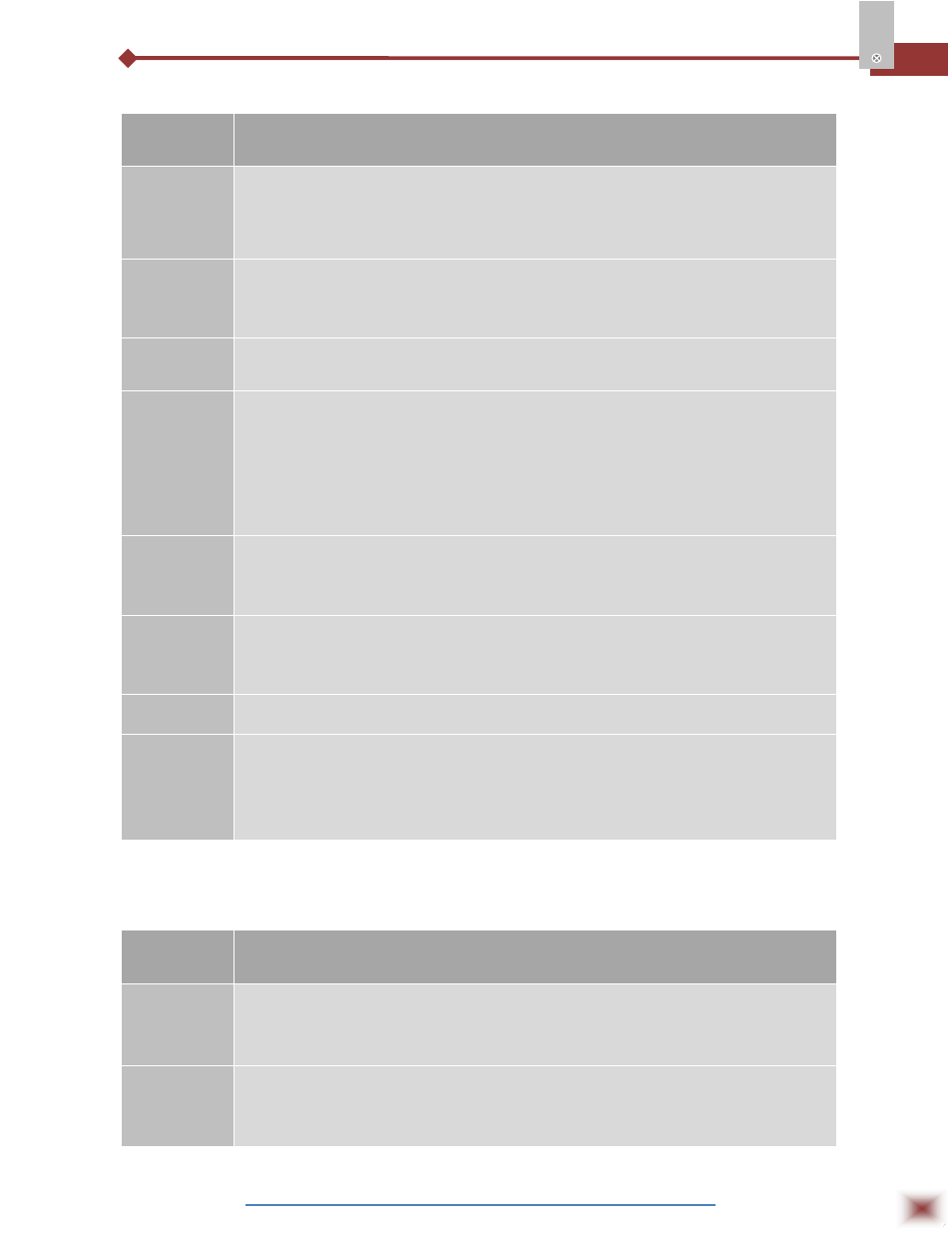
7.1.4 Configuration Cycle
PARAMETERS
PROMPT PARAMETER DESCRIPTION
In.typ
Input Type - Selects the input signal or sensor type to be connected to the PV
terminals. Refer to table 1 for options.
Changing this parameter will change all other parameters related to PV and
alarms, therefore it should be the first parameter to be set.
Dp.pos
Decimal Point Position - Defines the decimal point position in the displayed value. It
is displayed when linear input types 0-50mV, 4-20mA, 0-5V or 0-10V are selected at
the “in.tYP” prompt.
Vnit
Temperature Unit - Selects °C or °F indication. This prompt is not shown for input
types 0-50mV, 4-20mA, 0-5V or 0-10V is selected at the “in.tYP” prompt.
s.root
Square Root - This prompt is only shown for input type 0-50mV; 4-20mA and 0-5V
are selected at the “in.tYP” prompt.
Set “YES” and the square root will be applied to the measured value within the limits
programmed in “in.LoL” and “in.kiL”.
The display will show the low limit value should the input signal be below 1% of the
range.
In.lol
Input Low Limit - Sets the low limit for input type 0-50mV, 4-20mA, 0-5V or 0-10V.
When the PV Retransmission is used this limit defines the corresponding 4mA (or
0mA) in relation to the input value.
In.kil
Input High Limit - Sets the high limit for input type 0-50mV, 4-20mA, 0-5V or 0-10V.
When the PV Retransmission is used this limit defines the corresponding 20mA in
relation to the input value.
Ovt.ty
Analog Output Type - Selects the analog output type to either 0- 20mA or 4-20mA.
Ovt.er
4-20 mA Output behavior in case of failures – Defines the output as 4-20 mA when
there is an error in the indication.
Do – Applies a value < 4 mA;
UP – Applies a value > 20 mA
7.1.5 Customized Linearization Cycle
PARAMETERS
PROMPT PARAMETER DESCRIPTION
Inp.01
Inp.20
Defines the extreme points (lower and upper) of the customized linearization. Values
must be in the input signal unit:
0-50 mV, 4-20mA or 0-5V. For 0-10V select 0-5V.
Ovt.01
ovt.20
Defines the proportional indications in respect to each segment of the customized
linearization. Values are in desired indication unit (within the Indication Lower and
Upper Limits).