ABUS Technologies A1500 Universal Process Indicator User Manual
Page 7
ABUS TECHNOLOGIES INC.
7
A1500
6.1 Recommendation
1. Input signal wires should be laid out away from power lines and preferably inside grounded
conduits.
2. Instrument mains (line) supply should be suitable for this purpose and should not be shared.
3. In controlling and monitoring applications, possible consequences of any system failure must be
considered in advance. The internal alarm relay dos not warrant total protection.
4. RC filters (47 and 100nF, serial) are highly recommended for valve and contactor coils, etc.
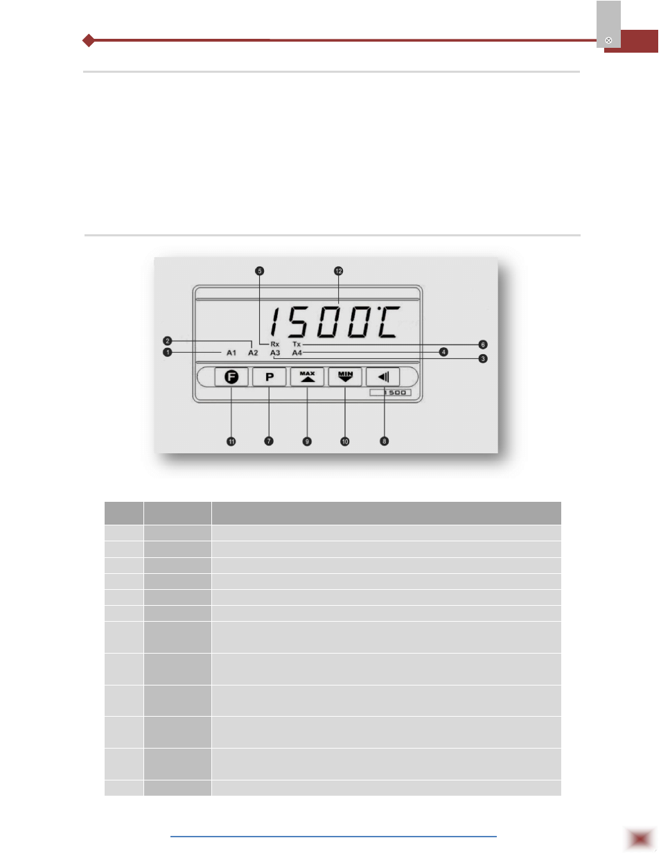
6.2 Panel
Panel Attribute
S.No. Parameters
Description
1
A1
Show active alarms.
2
A2
Show active alarms.
3
A3
Show active alarms.
4
A4
Show active alarms.
5
Rx
Indicate RS485 communication line is active.
6
Tx
Indicate RS485 communication line is active.
7
P
Program Key: This key is used to access different displays with the
programmable parameters of the device.
8
◄
Back Key: This key is used to go back to the previous parameter
displayed in the menu cycle.
9
▲
UP / MAX Key: This key is used to increase parameter value, as well
as to display maximum values stored in memory.
10
▼
DOWN / MIN Key: This key is used to decrease parameter value, as
well as to display minimum values stored in memory.
11
F
This special function key is used for pre-programmed functions as
explained in the SPECIAL FUNCTION KEY section of this manual.
12
Display
Shows the process variable (PV) and the programming prompts.