Dimensions, Ordering details, Connections – ABUS Technologies A1500 Universal Process Indicator User Manual
Page 5
ABUS TECHNOLOGIES INC.
5
A1500
3. DIMENSIONS
PANEL
DIMENSION
CODE
PANEL
DIMENSION
CASE DIMENSION
HOLE
CUTOUT
DIMENSION
W
H
W
H
D
W
H
A1500
96
48
90
44
100
92
45
4. ORDERING DETAILS
The standard unit includes 2 SPDT relays, 1 digital input and 24 Vdc (A1500) or 10
Vdc (A1500LC) supply output.
Option 1
: 2 SPST alarm relays (ALM3 and ALM4).
Option 2
: 4-20 mA / 0-20 mA analog output.
Option 3
: RS485 Modbus communication interface.
Option 4
: 24 Vac/Vdc power supply input.
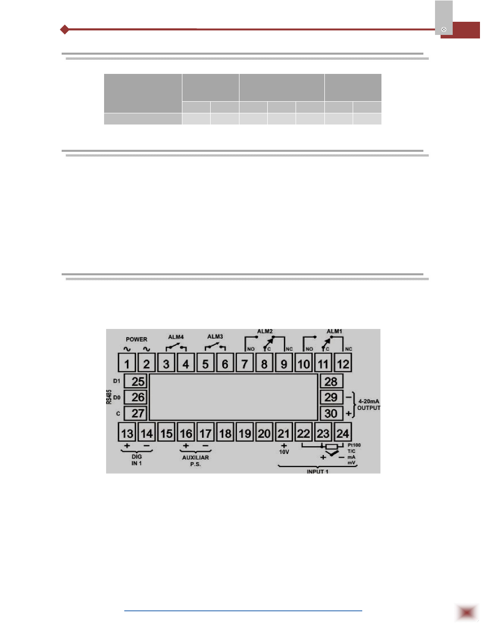
5. CONNECTIONS
The internal electronics can be removed from the front panel without any cable
disassembly. The input signals and power connections are shown in Figure 2.
Figure 2 – Back Panel Terminals
Sensor or input signal connection
These connections should be well done and terminals must be well tightened.
Thermocouples must be installed with proper extension or compensation cables.
Pt100 RTDs must be 3-wire connected and the wires connected to terminals 17
and 18 should have the same electrical resistance (same wire gauge) for proper
cable distance compensation.
Four-wire RTDs can be connected by disconnecting the fourth wire. Two-wire
RTDs can be connected by shortening terminals 22 and 23 and connecting the
Pt100 to terminals 16 and 17.