Installation – ABUS Technologies A1500 Universal Process Indicator User Manual
Page 6
ABUS TECHNOLOGIES INC.
6
A1500
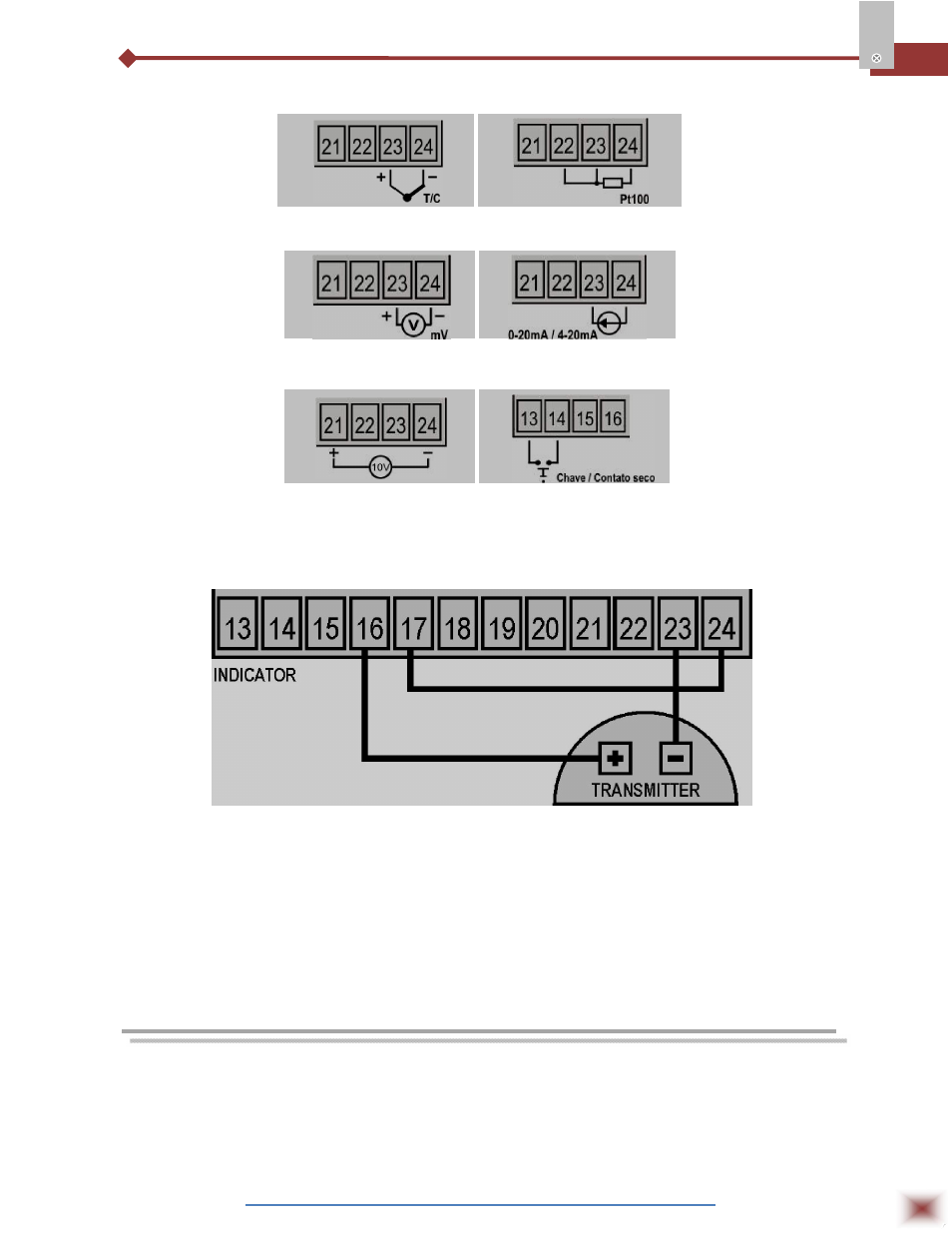
Figures below show how connections are made for each type of input.
Figure 5 – Voltage Connection
Figure 6 – Current Connection
Figure 7 – Connection for 0-
10V
Figure 8 – Digital Input
Figure 9 shows connections made to measure signals from a 4-20mA
transmitter supplied by the 24 V power supply, the indicator provides.
Figure 9 – Two-wire transmitter with internal power supply
5.1
Digital Input (Dig In)
The digital input can be used by connecting a switch (or equivalent) to its terminals, as shown in
Figure 8 above.
5.2
Analog output
The analog output of A1500 can be 0-20 mA or 4-20mA, which can be selected during
programming. This output is available at terminals 29 and 30.
6. INSTALLATION
The indicator must be attached to a panel. Remove the two plastic fixing clamps
from the instrument. Insert the unit into the panel cut-out and put back the fixing
clamps from the rear.
Figure 3 – Thermocouple
Connection
Figure 4 – 3 wire Pt100
Connection