Maintenance – ABUS Technologies A1500 Universal Process Indicator User Manual
Page 16
ABUS TECHNOLOGIES INC.
16
A1500
9. MAINTENANCE
9.1 Troubleshooting
Connection errors or improper configuration will result in malfunctioning of the indicator.
Carefully revise all cable connections and programming parameters before operating the unit. Some
error messages will help the user identify possible problems.
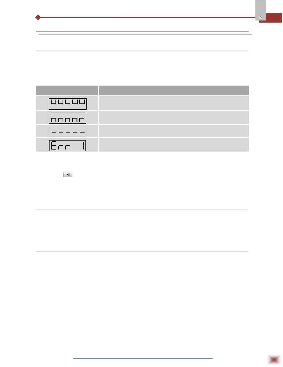
MESSAGE
POSSIBLE PROBLEM
Measured value is above the programmed sensor or input signal limit.
Measured value is below the programmed sensor or input signal limit.
Open input. No sensor is connected or the sensor is broken.
Pt100 cable resistance is too high or the sensor is badly connected.
Different messages other than the ones above should be reported to the manufacturer. Please
inform the serial number if this should occur. The serial number can be viewed at the display by
pressing the
key for about 3 seconds. The software version of the instrument can be viewed at the
time the unit is powered. The instrument might display false error messages especially concerning the
type of input selected.
9.2 Special Recommendations
Should the indicator be repaired, some special handling care should be taken. The device must
be withdrawn from the case and immediately placed in an anti-static wrap; protected from heat and
humidity.
9.3 Input Calibration
Should calibration of some scale be necessary, proceed as it follows:
1. Program the indicator with the type of input requiring calibration;
2. Program the high and low limits of the measure (in.lol and in.kil) for the extreme of the type of
input programmed;
3. Assign the input a corresponding signal and a know indication/measure and slightly over the low
limit of the indication/measure;
4. Access the “
inLo
“parameter. Use the MIN and MAX keys to select the expected values;
5. Assign the input a corresponding signal and a known indication and slightly below the higher limit of
the indication/measure;
6. Access the “
inki
“parameter. Use the MIN and MAX keys to select the expected values;
7. Repeat steps c to f until no new adjustment is necessary.
Note: When verifications are preceded, note if the Pt100 excitation/activation current the calibrator
requires is compliant to the Pt100 excitation current used in this instrument: 750µA.