Setting up the pdn tool, Setting up the pdn tool -2, Figure 1–1 – Altera Power Delivery Network User Manual
Page 6: And the capacitor mounting inductance (l
1–2
Chapter 1: Power Delivery Network (PDN) Tool User Guide
Setting Up the PDN Tool
Power Delivery Network (PDN) Tool User Guide
© March 2009
Altera Corporation
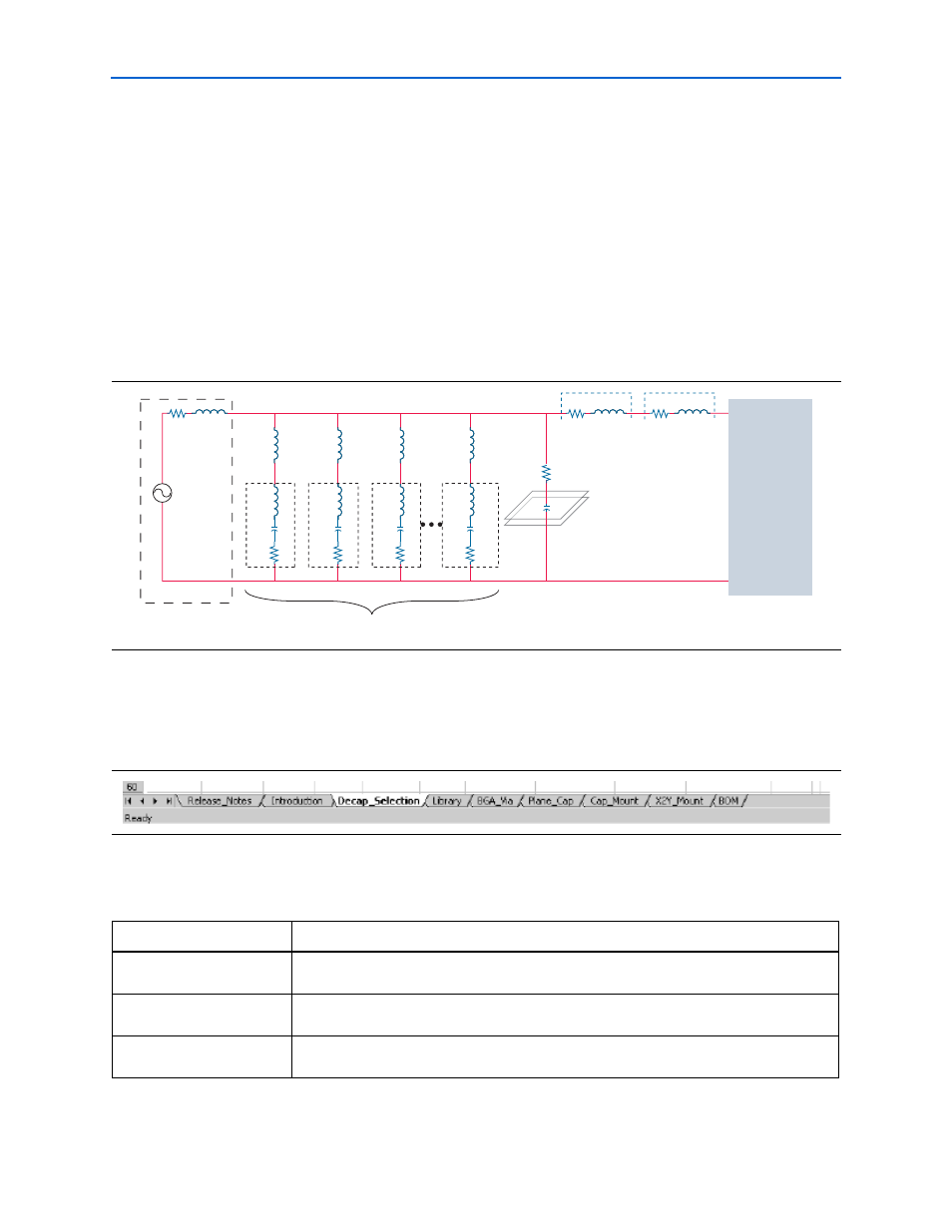
Beyond lower frequencies, the VRM impedance is primarily inductive, making it
incapable of meeting the transient current requirement. The on-board discrete
decoupling capacitors must provide the required low impedance from low to high
frequencies, depending on the capacitor intrinsic parasitics (R
cN
, C
cN
, L
cN
) and the
capacitor mounting inductance (L
mntN
). The interplanar capacitance between the
power-ground planes typically has lower inductance than the discrete decoupling
capacitor network, making it more effective at higher frequencies (tens of MHz). The
effectiveness of the decoupling capacitors is limited by the PCB spreading inductance
and the ball grid array (BGA) via inductance that a given capacitor encounters with
respect to the FPGA. To simplify the circuit topology, the PDN tool models the
distributed nature of PCB spreading, BGA inductance, and resistance with a single
lumped inductor and resistor.
Setting Up the PDN Tool
shows the various tabs of the PDN tool spreadsheet.
describes the PDN tool tabs.
Figure 1–1. PDN Circuit Topology
Altera FPGA
Device
BGR Via
R and L
Spreading
R and L
Planar
R and C
Rp
Cp
Lv
Rv
Ls
Rs
LmntN
Lmnt3
Lmnt2
Lmnt1
LcN
CcN
RcN
Lc3
Cc3
Rc3
Lc2
Cc2
Rc2
Lc1
Cc1
Rc1
Decoupling
CAP Model
Lvrm
Rvrm
VRM
VRM Model
Figure 1–2. Tabs in the PDN Tool
Table 1–1. Description of Tabs in PDN Tool (Sheet 1 of 2)
Tab
Description
Release Notes
This tab provides the legal disclaimers, the revision history of the tool, and the user
agreement.
Introduction
This tab shows the schematic representation of the circuit that is modeled as part of the PDN
tool. The tab also provides a brief Quick Start instruction on using the tool.
Decap Selection
This tab provides an interface to input the various parameters and observe the resultant
impedance profile. This is the main user interface to the tool.