Installation – Nexen TC920V 964356 User Manual
Page 7
4
FORM NO. L21268-C-1013
3. INSTALLATION
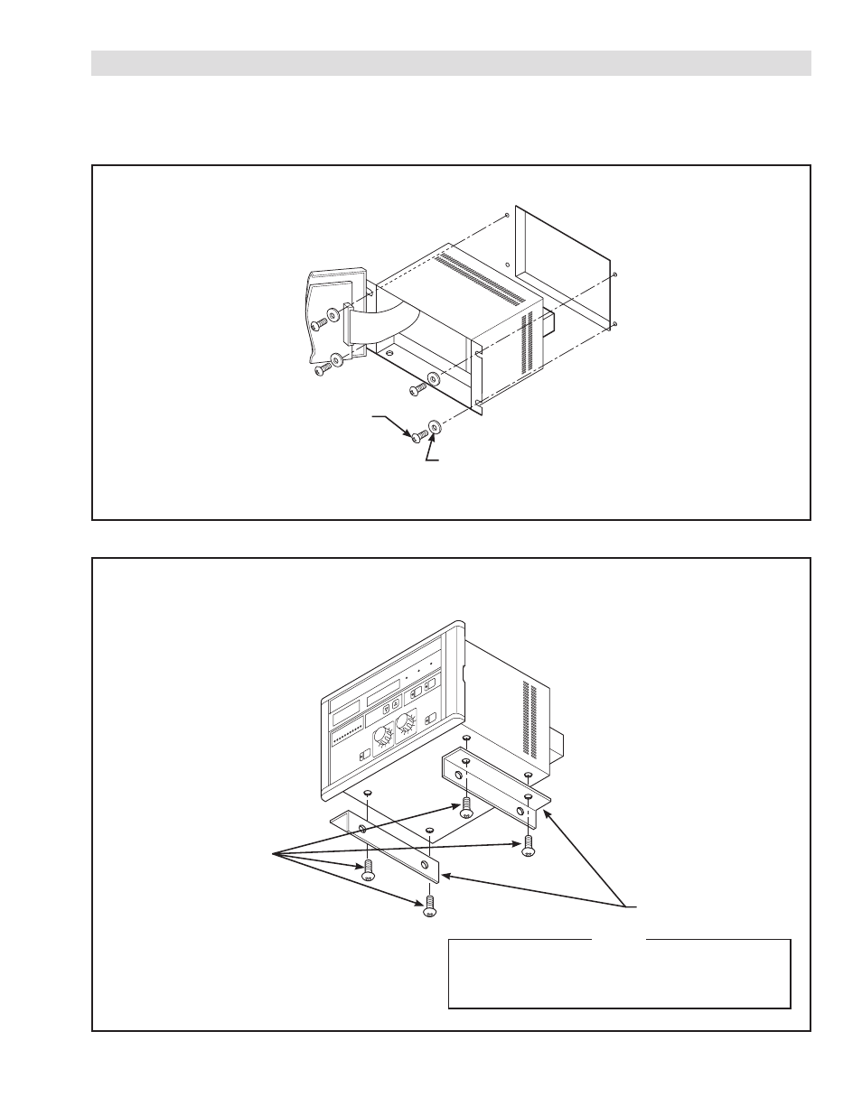
3.1 PHYSICAL MOUNTING
The TC920V should be installed on a flat surface or in a panel where it can easily be adjusted and maintained. Angle sup-
ports are included and may be installed as illustrated below for stand alone mounting.
FIGURE 3.1
Panel Mounting Installation Diagram of Controller
FIGURE 3.2
Stand-Alone Mounting Installation Diagram
Washer M5 (4 pieces)
(supplied by customer)
Angle Supports (2 pieces)
Fixing Screw for
Angle Supports
M4 x 6 (4 pieces)
Screw M5 x 8 (4 pieces)
(supplied by customer)
NOTE
When using Angle Supports, use only the
screws provided. Longer Screws may damage
internal components.