Basic setup, 1 start operation – Nexen TC920V 964356 User Manual
Page 23
20
FORM NO. L21268-C-1013
6. BASIC SETUP
The TC920V has several operating modes available. A machine setup will require the selection of the Start Mode, Stop
Mode, and optional Taper Mode depending on the machine setup and tension requirements. Refer to section 4.4 for
details on parameter adjustment.
6.1
START OPERATION
Start Mode sets the behavior of the control output when
transitioning to Automatic from a Stop condition, while the
“START” indicator lamp is lit.
The following parameters are related to this mode selection:
• No. 40
Start Mode
• No. 1
Start Level
• No. 2
Start Time
Mode 0: During the START condition, the parameter No.
1 (Start Level) is output as a fixed value.
Mode 1(default): The output value based on the MANual
output setting on the front panel, becomes the start level.
Select this mode when the level is to be changed frequently
by the operator.
Mode 2: Start Mode 2 is effective for machines which re-
quire multiple Start/Stop operations during the processing
of a complete roll. This mode will provide more consistent
tension during startups than Mode 0 or 1. The output value
just preceding a stop is automatically stored in memory and
this value is output during the start period. For a new roll,
the memory reset contact is required to reset the start level.
After momentarily applying the memory reset contact, the
start level is set to the ouput value based on the MANual
dial on the front panel.
The output value is not directly the value preceding the
start, but is a percentage of the stored value using the
following formula:
Mode 3: Diameter Based Start Level (Analog Diam-
eter Measurement)
In this mode, the start level is based on the measured roll
diameter and tension set point. Set the start level using
Equation 6.1 where maximum diameter is the measured
diameter at an input of 10.0V. If the sensor will not output a full 10V at full diameter, the equivalent diameter at 10V must
still be calculated. The start level for a given diameter and tension set point can be calculated by Equation 6.2. The analog
diameter input is on terminal 52. To use the analog diameter input, it is necessary to set MSW1–2 to Enabled as detailed
in section 4.5.
Mode 4: Diameter Based Start Level (Digital Diameter Measurement)
In this mode, the start level is based on the measured roll diameter and tension set point. Set the start level using Equation
6.1 where maximum diameter is the diameter set in Parameter No 39. The start level for a given diameter and tension set
point can be calculated by Equation 6.2. The digital diameter measuring function using an encoder is input into external pin
52. To use the digital diameter measuring function, it is necessary to set MSW0–3 to Enabled as detailed in section 4.5.
Current Start
Output Value (%) =
Previous Value x Start Level (%)
100
Start Level % =
Tension Full Scale(N) x Maximum Diameter (mØ)
2 x Rated Torque of the Operating Unit (N)
• 100
Control Output % = Start Level % x
Measured Diameter
x Tension Set Point
Maximum Diameter Full Scale Tension
Equation 6.1 Setup Diameter Based Start Level
Equation 6.2 Diameter Based Start Level
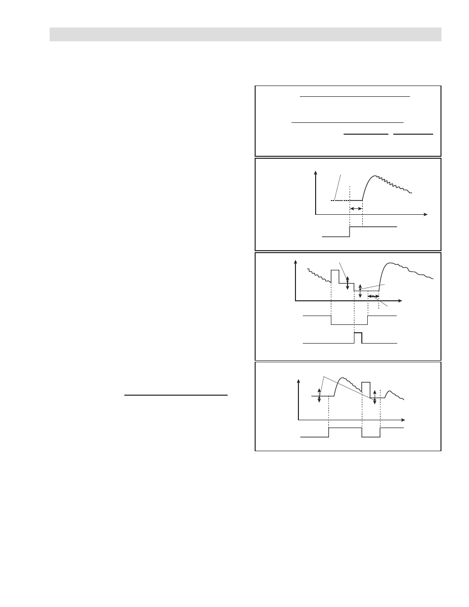
FIGURE 6.1 Start Sequence Diagram of Mode 0 & 1
FIGURE 6.2 Start Sequence Diagram of Mode 2
FIGURE 6.3 Start Sequence Diagram of Mode 3/4
Mode 0: Set by parameter No.1
Mode 1: Set by manual setting
Control output
Start timer
Automatic Contact
OFF ON
Stored Value: Varied by Start Level
Control Output
Start Timer
Same as mode 1
Memory Reset
Contact
Automatic
Contact
OFF
ON
ON
ON
Control Output
Changes in proportion to the diameter.
Reference value is varied by Parameter No. 1
Automatic
Contact
OFF
OFF
ON
ON