Tc920v unit descriptions (continued...) – Nexen TC920V 964356 User Manual
Page 6
3
FORM NO. L21268-C-1013
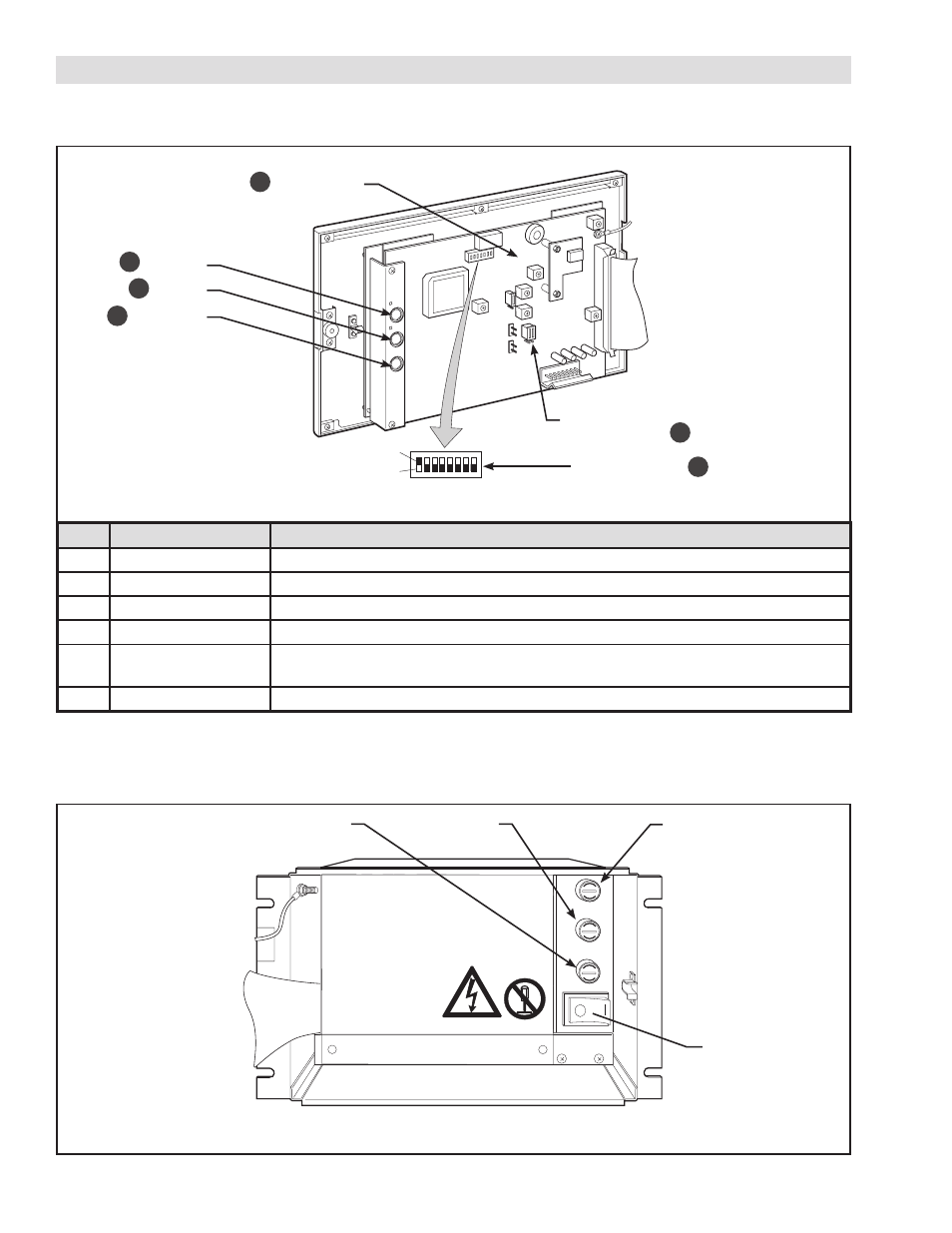
2.2 MAIN BOARD
Open the front panel to access the Main Board located on the backside of the front panel.
2.3 POWER SWITCH & FUSES
Open the front panel to access the power switch and fuses on the inside of the unit. Refer to section 12 for fuse mainte-
nance instructions.
Item
Name
Function
1
DATA Key
Pressing key enters setup mode.
2
SET Key
Commits a change in setup mode.
3
CLEAR Key
Changes entry digit in setup mode.
4
DIP Switch (SW1)
Select basic operation mode. (Refer to section 3.4 for details.)
5
Tension Sensor
Selection Jumper
Select PH1/PH2 for use with MB/SW Tension Sensor.
Select AW1/AW2 for use with TSA Tension Sensors.
6
LCD Contrast Adjust Turn potentiometer (VR1) to adjust the contrast of the LCD Display when necessary.
FIGURE 2.2
Main Board
FIGURE 2.3 Power Switch & Fuses
2. TC920V UNIT DESCRIPTIONS (continued...)
ON
OFF
12345678
CM2
VR104
VR103
VR1
VR2
VR3
VR4
JP104
JP101
JP102
JP103
SET
DATA
CLEAR
CM1
Power
Fuse
Fuse 3
Fuse 2
Power Switch
Sensor Selecting
Jumper (JP 103)
Switch No. (SW1)
LCD Contrast
Adjustment
CLEAR Key
SET Key
DATA Key
1
5
4
6
3
2