Basic setup (continued...), 3 taper tension operation – Nexen TC920V 964356 User Manual
Page 25
22
FORM NO. L21268-C-1013
6. BASIC SETUP (continued...)
6.3
TAPER TENSION OPERATION
Taper tension when used in a winding operation allows for the tension to be greater at the core of the roll. The primary
behavior of taper tension is set by the Taper Ratio, which defines the reduction in tension at the outer diameter of the roll.
Taper Modes 1 and 2 make use of internal taper compensation without use of external sensors. Taper Modes 3 and 4 make
use of an external diameter input providing more accurate taper operation. The following parameters control the operation
of taper tension: • No. 42: Taper Mode
• No. 14: Taper Ratio
• No. 15: Taper Start Point
• No. 16: Taper End Point
Taper Ratio =
[%]
1 x
τ
FS
x (T–T
E
)
25 x T x D
E
Taper Ratio =
[%]
1 x
τ
FS
x (T
S
–T)
25 x T x D
S
τ
FS
= Rated Torque (Nm)
T
= Set Tension (N)
T
E
= End Tension (N)
D
E
= End Diameter (m)
τ
FS
= Rated Torque (Nm)
T
= Set Tension (N)
T
E
= End Tension (N)
D
E
= End Diameter (m)
Mode 0 (default): Taper Operation Unused
Taper control is disabled regardless of taper ratio setting.
Mode 1: Internal Forward Taper
The control output is on the winding side; example being the
winder under control of a clutch. When the control output
exceeds Taper Start Point (parameter no. 15), taper ten-
sion becomes effective (Refer to Figure 6.7) .
Mode 2: Internal Reverse: When taper is performed by
the tension of the unwind side instead of the tension on the
winding side (Refer to Figure 6.8).
Mode 3: Analog Diameter Based Taper Tension
Taper tension is controlled by the external analog diameter
measurement. Set Taper Ratio to the total desired reduc-
tion in tension setpoint due to taper tension. Set the Taper
Start Point and the Taper End Point to the percentage of
diameter where Taper Tension should begin and end, where
the analog input full scale is 100% (Refer to Figure 6.9).
Setting Example: Analog Input: Full Scale diameter of 20
inches. A 10% reduction in tension is desired, starting at
a core of 4 inches to 10 inches in diameter.
Taper Ratio:
10%
Taper Start Point: 20% (4 in / 20 in = 20%)
Taper End Point:
50% (10 in / 10 in = 50%)
Mode 4: Digital Diameter Based Taper Tension
Taper tension is controlled by the digital diameter mea-
surement. Set Taper Ratio to the total desired reduction
in tension setpoint due to taper tension. Set the Taper
Start Point and the Taper End Point to the percentage of
maximum diameter where Taper Tension should begin and
end (Refer to Figure 6.9).
Taper Start Point and Taper End Point are determined
based on the percentage of maximum diameter set by Maxi-
mum Diameter (Parameter No. 39). MSW0–3 must also
be turned on to enable the diameter measurement function.
Setting Example: Maximum Diameter (Parameter No.
39): 500mm. A 10% reduction in tension is desired,
starting at a core of 100mm to 250mm in diameter.
Taper Ratio:
10%
Taper Start Point: 20% (100mm / 500mm = 20%)
Taper End Point:
50% (250mm / 500mm = 50%)
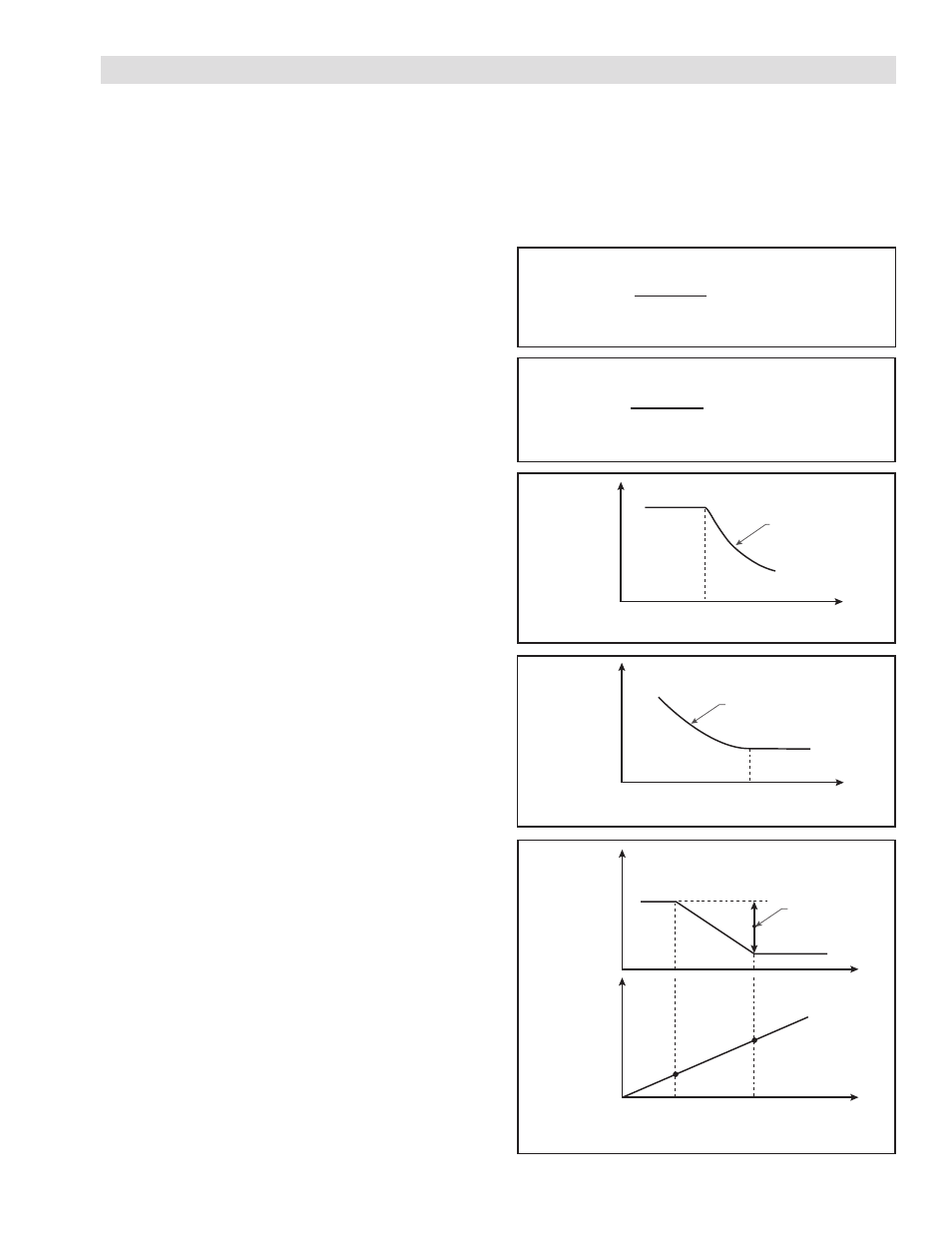
Equation 6.5 Taper Ratio Setup
Equation 6.6 Reverse Taper Ratio Setup
Figure 6.7 Tapering Sequence Diagram of Mode 1
Figure 6.8 Tapering Sequence Diagram of Mode 2
Figure 6.9
Tapering Sequence Diagram of Mode 3 & 4
Taper Start Point
Ta
ke-up Tension
Approximate
straight line
Taper Start Point
Feed Tension
Approximate
straight line
Taper start point Taper end point
Set tension
Diameter signal
Taper ratio