Advanced settings (continued...) – Nexen TC920V 964356 User Manual
Page 31
28
FORM NO. L21268-C-1013
7. ADVANCED SETTINGS (continued...)
7.4.3
e
mergenCy
S
toP
g
ain
C
orreCtion
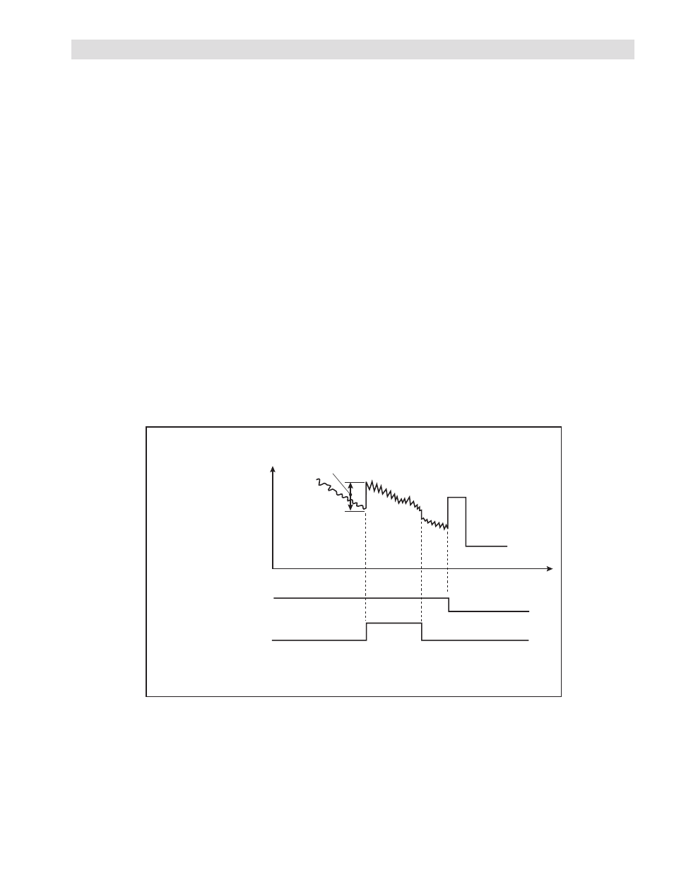
Emergency Stop Gain Correction operates in the same manner as the previously described Acceleration/Deceleration
Polarity Gain Correction in section 7.4.2 with a separate set of gain correction parameters. The Emergency Stop gain
correction is active while the Emergency Stop contact (Terminals 8 & 12) is ON. When the Emergency Stop contact is
turned ON, the Control Output is increased by the Emergency Stop Correction. When the Diameter Measuring Func-
tion is enabled, the effective Emergency Stop Correction is proportional to the measured diameter vs. maximum diameter;
otherwise the full Emergency Stop Correction is applied. While the Emergency Stop Contact is active, the Proportional
Gain and Integral Time are set by Parameters No. 34 – 37.
Activating Conditions
• Emergency Stop Contact is ON (Terminals 8 and 12)
• Memory DIP Switch (MSW0-1, 2): Set to “EMS” (default value)
Related Parameters
• Memory DIP Switch MSW0-3: Diameter Measuring Function
Disabled:
Full Emergency Stop Correction
Enabled:
Emergency Stop Correction proportional to maximum diameter
• No. 34
Proportional Gain 2 ( + deviation )
• No. 35
Integral Time 2 ( + deviation )
• No. 36
Proportional Gain 2 ( - deviation )
• No. 37
Integral Time 2 ( - deviation )
• No. 38
Emergency Stop Correction
FIGURE 7.4 Emergency Stop Sequence Diagram
Correction Factor
Control Output
Automatic Contact
Emergency Stop Contact
ON
OFF
ON