Electrical connections (continued...), Tcd 600 alarm output connection diagrams – Nexen TCD600E 912145 User Manual
Page 9
FORM NO. L-20348-F-0705
9
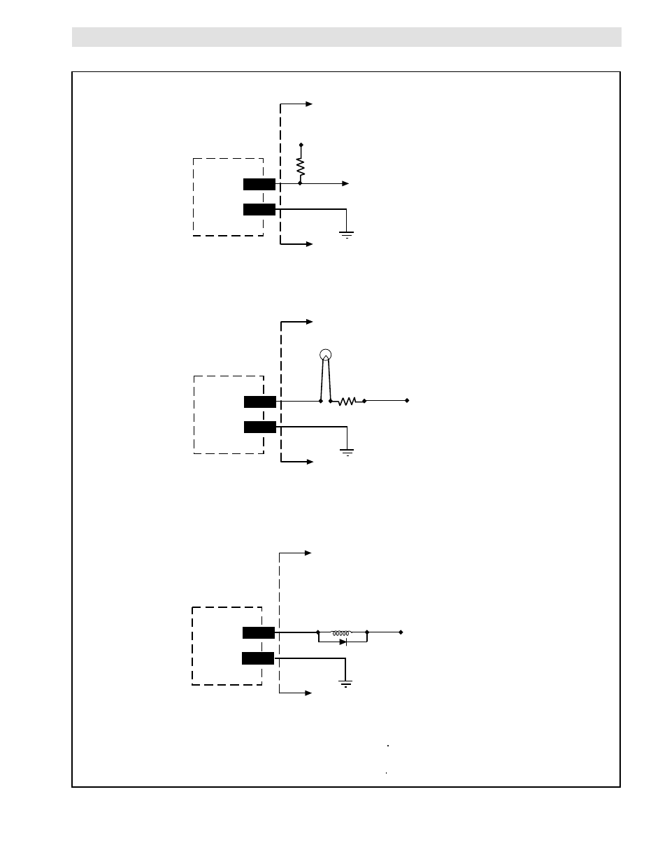
TCD 600 ALARM OUTPUT CONNECTION DIAGRAMS
FIGURE 10B
ELECTRICAL CONNECTIONS (continued...)
29/31
30/32
TCD 600
To PLC Input
VDC Common
VDC
(See Specifications for
maximum voltage.)
R
(See Note.)
User Supplied
User Supplied
NOTE: The minimum value of resistor (R) is 10 x VDC.
29/31
30/32
TCD 600
VDC Common
VDC
(See Specifications for
maximum voltage.)
(See Note.)
User Supplied
User Supplied
NOTE: The minimum value of Resistor (R) is equal to VDC
divided by the maximum current limit of the Indicator.
R
External Indicator
29/31
30/32
TCD 600
VDC Common
VDC
(See Specifications for
maximum voltage.)
(See Notes.)
User Supplied
User Supplied
NOTES: 1. Be sure the current requirement of the External Coil does not
exceed the capability of the alarm output (
2. Any inductive load, such as a relay coil, must have a 1N4002,
or equivalent, diode across it as shown.
External
Coil
1N4002
Alarm Output Tied to External Indicator
Alarm Output Tied to PLC Input.
Alarm Output Tied to External Inductive Coil