Installation, Caution, Panel mounting instructions – Nexen TCD600E 912145 User Manual
Page 5: Panel cutout dimensions controller positioning
FORM NO. L-20348-F-0705
5
7.25 In.
[184 mm]
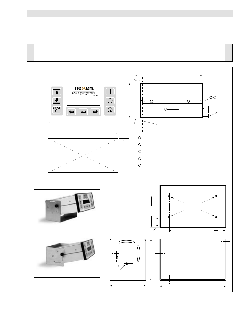
FIGURE 5
CAUTION
The TCD 600 is an electronic component and should be mounted in a shock and vibration free area which has
an ambient temperature of less than 120
o
F [50
o
C] and more than 32
o
F [0
o
C].
PANEL DIMENSIONS AND
MOUNTING INSTRUCTIONS
MOUNTING BRACKET DIMENSIONS
.50 In.
[13 mm]
3.77 In.
[96 mm]
7.56 In.
[192 mm]
7.28 In.
[185 mm]
3.63 In.
[92 mm]
5.31 In.
[135 mm]
4.63 In.
[118 mm]
4.0 In.
[102 mm]
2.0 In.
[51 mm]
.75 In.
[19 mm]
1.0 In.
[26 mm]
1
2
3
4
CONTROL PANEL
5
1
Remove the Retaining Screw with a 1/16" Allen wrench.
Pull the Slide Bars (on both sides) off the Case.
Slide the Case through the cutout in the control panel.
Push the Slide Bars back into the grooves of the Case.
Reinstall the Retaining Screws and tighten to squeeze
the Control Panel between the Slide Bars and the TCD
600 Bezel.
BEZEL
2
3
4
5
7.3 In.
[186 mm]
.203Ø
(Screws Provided)
.203Ø
Wall Mount Configuration
Desktop Configuration
PANEL MOUNTING INSTRUCTIONS
INSTALLATION
(continued...)
PANEL CUTOUT
Dimensions
CONTROLLER POSITIONING
The TCD 600 Controller should be mounted in a location that will allow convenient use for the operator.