Setup procedure (continued...) calibration mode – Nexen TCD600E 912145 User Manual
Page 15
FORM NO. L-20348-F-0705
15
8. The display returns to Set Job. Press EDIT again to edit
JOB 2, and repeat this procedure up to JOB 5 if needed.
Or, press Load to recall previously saved job settings to
use for a job you want to run now. Press the plus or minus
button to select Load, then press Enter (See Figure 24).
9. You can then choose to load either the default job or any of
5 previously saved jobs. Press the plus or minus button to
select the desired job (See Figure 25), then press Enter;
the display will confirm that the selected job is loaded, then
it will return to the Set Job Mode.
FIGURE 24
SET JOB (OFF)
Edit [Load] Save
FIGURE 25
LOAD JOB (OFF)
Default Job
NOTE: Diameter calibration for the ultrasonic sensor, is
only required for the initial setup of the machine, or if
the ultrasonic sensor has been moved.
To gain access to Machine setup and diameter calibra-
tion, press the Nexen logo button while simultaneously
pressing the STOP button and hold them until SETUP
ENABLE appears on the display (See Figure 11).
1. Using the Select Upper button, advance the top line of the
display to Calibration Mode (See Figure 26). Using the
plus or minus buttons, select Edit, then press the Enter but-
ton.
2. Diam will appear in the display (See Figure 27). Press
Enter.
NOTE: The following procedure (Steps 3-6) applies only to the
Ultrasonic Sensor. Advance to Step 7 to calibrate a Proximity
Switch Sensor or Proximity Switch-Encoder sensors.
3. Slide an empty core onto the roll shaft, so it is seen by the
Ultrasonic Sensor.
4. CAL DIAMETER, Core Diam: will appear in the display
(See Figure 28). Using the plus or minus button, enter de-
sired core diameter, then press the Enter button. Comput-
ing will appear in the display for a few seconds, then the
display will advance to the next step (See Figure 29).
5. Remove empty core, slide on a maximum-diameter roll so it
is seen by the Ultrasonic Sensor.
Rolls of less than the maximum diameter can be used. In
these instances, enter the actual diameter when prompted
for Max Diam.
6. CAL DIAMETER, Max Diam: will appear in the display (See
Figure 30). Using the plus or minus button, enter the maxi-
mum roll diameter then press the Enter button. Computing
will appear in the display for a few seconds (See Figure
29), then the display will return to the CAL MODE (See
Figure 26). Advance to Step 11 to enable lockout.
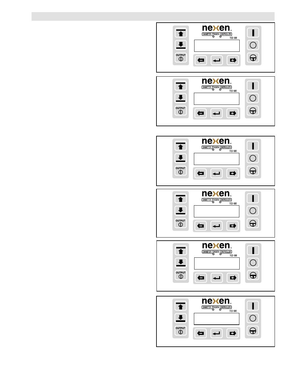
FIGURE 27
FIGURE 26
FIGURE 28
FIGURE 29
CAL MODE (OFF)
[Edit ] or Default
CAL MODE (OFF)
[Diam]
CAL DIAMETER
(OFF)
Core Diam: 001.00 in
CAL DIAMETER (OFF)
Computing
SETUP PROCEDURE (continued...)
Calibration Mode
(continued...)