Wiring schematics, Chillit chillers, Clw quad series chiller installation manual – WaterFurnace CLW Chiller User Manual
Page 13: Legend, Se-e1
13
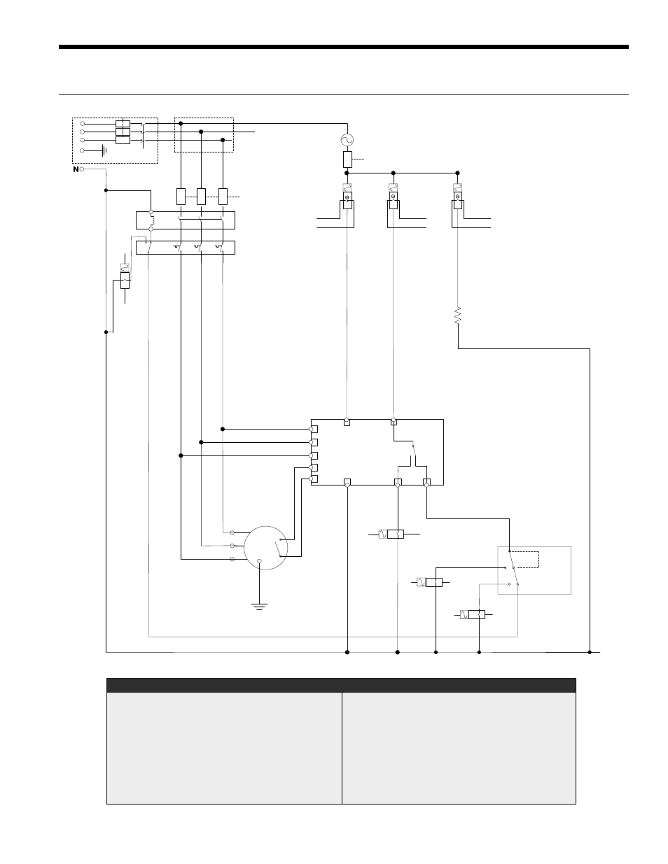
CLW QUAD SERIES CHILLER INSTALLATION MANUAL
Wiring Schematics
L1
L2
L3
1
2
L
11
N
12
14
L1
L2
L3
F1
F1 Main Fuse
F2 Compressor Fuse
K1 Motor Contactor
T/O Thermal Overload Relay
M Compressor Motor
F3 Control Circuit Fuse
RIB1 Enable Compressor Relay (HOA)
RIB2 Enable Crank Heater (HOA)
RIB3 Fault Reset (HOA)
BO1 Binary Controller Output (Enable Compressor)
BO2 Binary Controller Output (Crank Heater)
BO4 Binary Controller Output (Fault Reset)
LEGEND
Main
Switch
F2
K1
T/O
120V AC
M
1
2
3
F3
RIB3
N/C
RIB1
N/O
BO4
COM
BO1
COM
R1 Motor Protect Alarm Monitor Relay
R2 Thermal Overload Alarm Monitor Relay
R3 High Pressure Alarm Monitor Relay
R4 Low Pressure Alarm Monitor Relay
BI6 Binary Control Input 6 (Motor Protect & Thermal Overload)
BI7 Binary Control Input 7 (High Pressure Alarm)
BI8 Binary Control Input 8 (Low Pressure Alarm)
CK HTR Crankcase Heater
Note 1: Many different power connection configurations are available, refer to specifications.
RIB2
N/O
BO2
COM
R1
BI6
COM
Dual
Pressure
Switch
Low Pressure
High Pressure
R4
BI8
COM
R3
BI7
COM
CK HTR
R2
BI6
COM
120V
-
+
SE-E1
See Note 1
See Note 1
CHILLIT CHILLERS
(CLW SCROLL SERIES BASIC WIRING DIAGRAM)