Vortech Universal Big Block Carbureted System User Manual
Page 20
P/N: 4GA020-030
©2008 Vortech Engineering, LLC
All Rights Reserved, Intl. Copr. Secured
08DEC08 V3.0(BBC LowMount(4GA..030 V3.0))
12
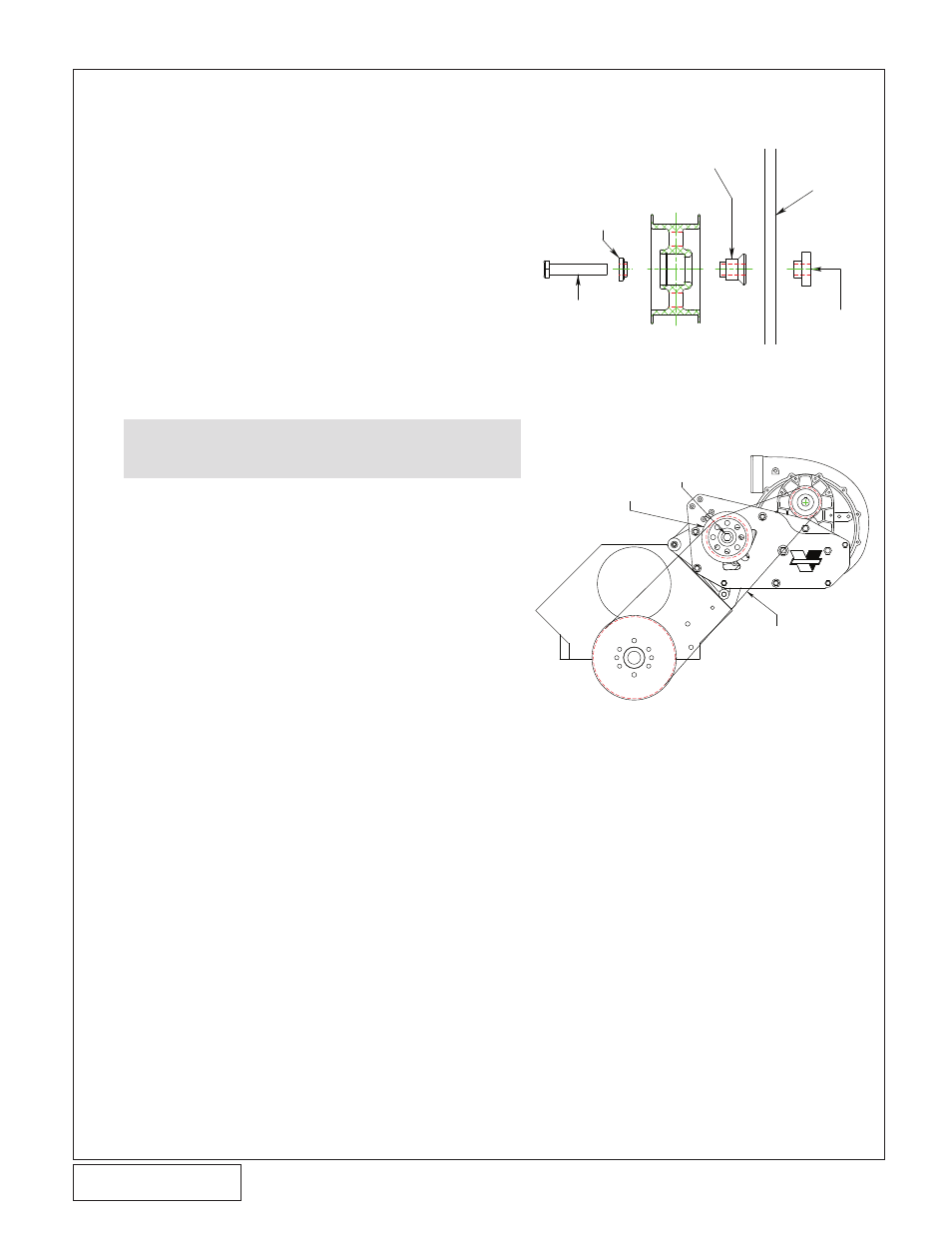
M12 X 1.75 X 65MM LONG
SCREW BEARING PILOT, SPACER,
AND SPECIAL MACHINED NUT
ALUMINUM TENSIONER IDLER
SUPERCHARGER DRIVE BELT
(INSTALLED AFTER
ACCESSORY BELTS)
M12 X 1.75 X 65MM BOLT
BEARING
PILOT
IDLER
IDLER
SPACER
MACHINE NUT SPECIAL
(PILOTS IN SLOT)
1/2” MOUNTING PLATE
Fig. 10-a (Cog Belt Tensioner Assembly - Side View)
Fig. 10-b (Cog Belt Route Only)
A. (Cog drive only) Slide the M12-1.75 X 65mm
screw through the supplied bearing pilot, alu-
minum idler and idler spacer. Place the
machine nut into the slot in the supercharger
support plate. Loosely attach the previously
assembled idler assembly, do not tighten at
this time. See Fig. 10-a
B. (Cog drive only) Fit the supercharger drive
belt over the new crank pulley, idler pulley
and supercharger pulley.
C. (Cog drive only) Tension the belt by pulling
up on the tensioner by hand and then tighten
the previously installed M12 hardware. The
belt does not need to be tightened excessive-
ly. See Fig. 10-b.
10. SUPERCHARGER DRIvE BElT INSTAllATION (v-4 "RACE" ONlY)
CAUTION: Do not "back-bend" a cog belt to tension.