Vortech Universal Big Block Carbureted System User Manual
Page 16
P/N: 4GA020-030
©2008 Vortech Engineering, LLC
All Rights Reserved, Intl. Copr. Secured
08DEC08 V3.0(BBC LowMount(4GA..030 V3.0))
8
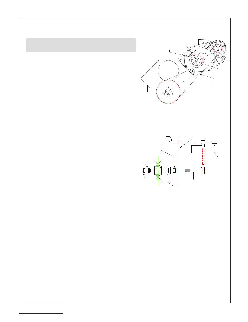
7. SUPERCHARGER DRIvE BElT INSTAllATION
(TWIN PlATE v-7 ONlY, v-4 RACE SKIP TO SECTION 8)
A. Attach the supplied belt tensioner adjustment
screw, tensioner arbor and adjustment screw
locator block to the supercharger support
plate as show in figure 7-a. Secure the
assembly to the plate by threading the two
1/4-20 x 1” flat head allen screws through the
plate and into the adjustment screw locator
block as shown.
B. Slide the arbor bushing (Ø.75”OD x Ø.530”ID
x .490” long) onto the arbor screw. Verify that
the bushing fits in the arbor slot up against
the arbor screw head. Place the idler spacer
(4GA017-011) and aluminum tensioner idler
onto the arbor screw, secure using the pro-
vided bearing pilot (4FD017-011) and sup-
plied 1/2"-20 hex nut.
C. Fit the supercharger drive belt over the new
crank pulley and supercharger pulley.
D. Tension the belt by using a 3/8” socket to
turn the tensioner adjustment screw anti-
clockwise until the desired tension is
achieved. Secure the tensioner idler by tight-
ening the 1/2"-20 hex nut previously installed.
Fig. 7-a (10-Rib Belt Route Only)
ALUMINUM TENSIONER IDLER
1/2”-20 HEX NUT AND BEARING
PILOT (4DF017-011)
SUPERCHARGER DRIVE
BELT (INSTALLED AFTER
ACCESSORY BELTS)
4GA010-061
CAUTION: Cog tensioner assembly does not use the ten-
sioner arbor method. For cog drive applications
skip to 7-e
1/4-20 X 1” SCREW
ARBOR SPACER
(SLIDES OVER ARBOR)
IDLER
BEARING
PILOT
1/2”-20
HEX NUT
IDLER
SPACER
1/2” MOUNTING PLATE
IDLER
ADJUST
SCREW
BELT TENSIONER ARBOR
IDLER ADJUST
SCREW BRACKET
Fig. 7-b (10-Rib Belt Tensioner Assembly - Side View)