Vortech Universal Big Block Carbureted System User Manual
Page 13
P/N: 4GA020-030
©2008 Vortech Engineering, LLC
All Rights Reserved, Intl. Copr. Secured
08DEC08 V3.0(BBC LowMount(4GA..030 V3.0))
5
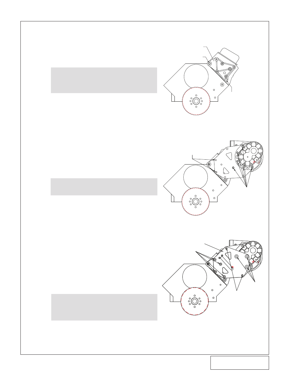
A. Mount the supplied aluminum supercharger
mounting bracket onto the front of the driver’s
side cylinder head using the two 7/16-14 x 2"
socket head screws and one 7/16-14 x 4.25"
screw with washer as shown in Fig. 5-a.
B. Loosely attach the supplied supercharger
mounting plate (4GA010-051) to the previ-
ously installed mounting bracket using one of
the supplied 3/8-16 x 1.25” hex head screw
and washer as shown in fig. 5-b. Temporarily
install two of the supplied 3/8-16 x 2-3/4” hex
head screws through the supercharger
mounting plate as a guide. Tighten the 3/8-16
x 1.25” hex head screw at this time. Remove
the two 3/8-16 x 2-3/4” hex head screws.
C. Remove the blue plastic oil drain cap located
on the fitting at the bottom of the supercharg-
er unit and install the supplied 1/2" (fabric
braided) oil drain hose. Secure with a #8
hose clamp.
D. Install the supercharger to the mounting
plate. Secure the unit to the plate with the
five supplied 3/8-16 x 1.25" screws and AN
flat washers.
E.
Loosely install the supercharger support plate
(4GA010-061) using the four 3/8-16 x 2.75”
screws, washers and four of the Ø.75” x
1.309” long spacers (2A017-049) provided.
Install the two remaining Ø.75” x 1.309” long
spacers (2A017-049) using the two 3/8-24 x
2.75” screws and washer. Finally install the
three M12-1.75 x 20mm thin head screws
with washers as seen in figure 5-e. Tighten
all hardware installed to this point.
F.
Route the drain hose down to the previously
installed fitting in the oil pan and secure with
a #8 hose clamp. Trim hose if necessary.
NOTE:
Some Gen IV and earlier heads (includ-
ing “GM performance” heads) require
3/8-16 screws and flat washers to be
used in lieu of the 7/16" hardware. Both
sizes have been included in the mount-
ing bracket assembly.
5. SUPERCHARGER MOUNTING (TWIN PlATE v-7 ONlY, v-4 SKIP TO SECTION 8)
NOTE:
Oil drain hose must be routed downhill
with minimal bends and no kinking. The
supercharger relies on a gravity drain for
proper operation. Uphill hose routing will
result in improper drainage and possibly
supercharger failure.
CAUTION: Clock the clamp screw housing to the
side so that it does not interfere with
the mounting plate during installation.
Fig. 5-a
Fig. 5-b
TEMPORARILY INSTALL TWO
3/8-16 X 2.75” HEX HEAD SCREWS
3/8-16 X 1.25 HEX
HEAD SCREW AND
WASHER
4GA010-051
3/8-16 X 2.75 HEX HEAD
SCREW AND WASHER
3/8-24 X
2.75” HEX
HEAD
SCREW AND
WASHER
M12 X 1.75 X
20MM HEX
HEAD SCREW
AND WASHER
4GA010-061
Fig. 5-E
7/16-14 X 4.25
HXHD SCREW
VORTECH SUPERCHARGER
MOUNTING BRACKET
2 PLACES 7/16-14 x 2" SH SCREW