Vortech Universal Big Block Carbureted System User Manual
Page 18
P/N: 4GA020-030
©2008 Vortech Engineering, LLC
All Rights Reserved, Intl. Copr. Secured
08DEC08 V3.0(BBC LowMount(4GA..030 V3.0))
10
8. SUPERCHARGER MOUNTING RACE (v-4 RACE BRACKETS ONlY. TWIN PlATE
v-7 SKIP TO SECTION 11)
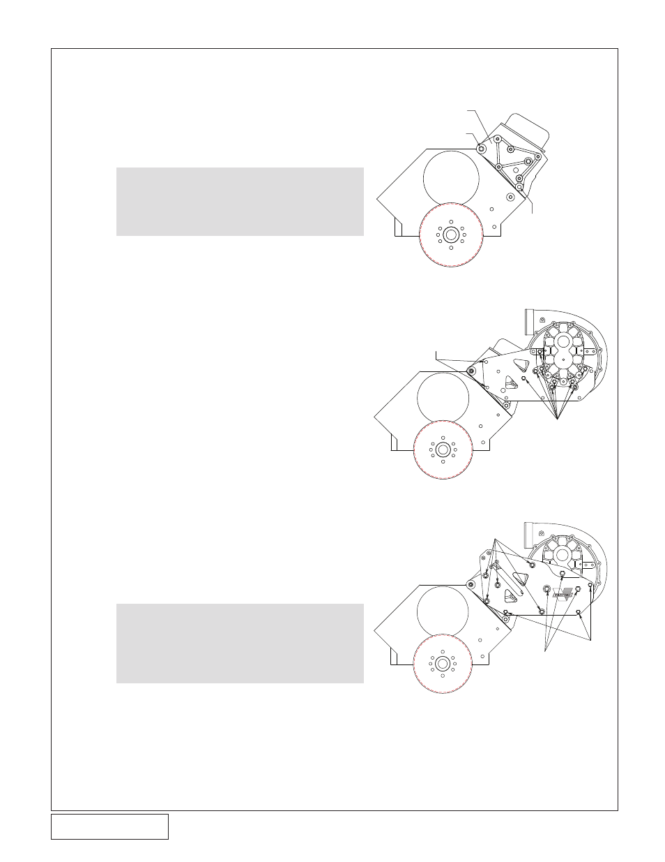
A. Mount the supplied aluminum supercharger
mounting bracket onto the front of the driver’s
side cylinder head using the two 7/16-14 x 2”
socket head screws and one 7/16-14 x 4.25”
screw with the washer as shown in Fig. 8-a
B. Loosely attach the supplied supercharger
mounting plate (4GA010-071) to the previous-
ly installed mounting bracket using one of the
supplied 3/8-16 x 1.25” hex head screws and
washer as shown in fig. 8-b. Temporarily
install two of the supplied 3/8-16 x 2-3/4”hex
head screws through the supercharger
mounting plate as a guide. Tighten the 3/8-16
x 1.25” hex head screw at this time. Remove
the two 3/8-16 x 2-3/4” hex heads screw.
C. Secure an oil drain line to the bottom of the
supercharger in a manner that will not inter-
fere with the supercharger support bracket.
NOTE: There is no oil drain line supplied in
the Race bracket kit.
D. Install the supercharger to the mounting plate.
Secure the unit to the plate with the eight sup-
plied 3/8-16 x 1.25” screws and AN flat wash-
ers. See Fig. 8-b
E.
Loosely install the supercharger support plate
(4GA010-081) using the five 3/8-16 x 2.75”,
three 3/8-16 x 3” screws, eight Ø1.309” long
spacers (2A017-049) and washers provided.
Finally install the three M12-1.75 x 20mm thin
headed screws as seen in figure 8-c. Tighten
all hardware installed to this point.
F.
Route the oil drain hose down to your prede-
termined location and secure.
NOTE:
Some Gen IV and earlier heads (includ-
ing “GM performance” heads) require 3/8-
16 screws and flat washers to be used in
lieu of the 7/16” hardware. Both sizes
have been included in the mounting
bracket assembly.
NOTE:
You will need to provide and adequate oil
drain from the supercharger to the oil pan
or oil collection reservoir. The oil path
should maintain a down hill direction and
be free of any dips or kinks. The oil
should enter the pan/reservoir above the
oil level to maintain a free flowing path.
3/8-16 x 1.25”
HEX HEAD
SCREW AND
WASHER
TEMPORARILY INSTALL
TWO 3/8 X 2.75” HEX
HEAD SCREWS
4GA010-071
Fig. 8-B
3/8-16 X 2.75” HEX
HEAD SCREW AND
WASHER
M12 X 1.75 X
20MM HEX
HEAD SCREW
AND WASHER
3/8-16 X 3.0”
HEX HEAD
SCREW AND
WASHER
4GA010-081
®
Fig. 8-C
Fig. 8-A
7/16-14 X 4.25
HXHD SCREW
VORTECH SUPERCHARGER
MOUNTING BRACKET
2 PLACES 7/16-14 x 2" SH SCREW