Vortech 1996-2004 Ford 4.6 Mustang GT User Manual
Page 35
A.
Slide the 3" sleeve and #48 hose clamps onto
the throttle body. Slide the 2-3/4" sleeve and
#44 hose clamps onto the supercharger
discharge.
B.
Install the supplied 1" x 90° rubber elbow to
the 1" bung on the supercharger discharge
tube using a #16 hose clamp. Insert the plastic
1" hose union fitting into the remaining end of
the rubber elbow. (See Fig. 10-d.)
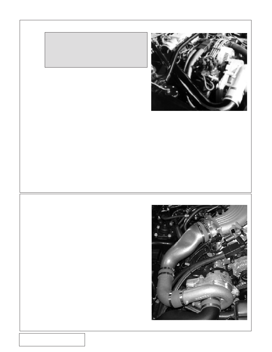
*C. Install the discharge tube assembly. Align the
bypass valve, all hoses and tighten all clamps.
(See Fig. 11-a.)
**D. Join the end of the plastic hose union to the 1"
bypass inlet hose installed in Step 10. Secure
all hoses with the supplied #16 hose clamps.
E.
Route the 5/32" vacuum line to the bypass
valve and TEE into the FMU vacuum line with
the supplied 5/32" TEE.
F.
Route the 5/32" vacuum line from the bypass
valve over to the fuel pressure sensor and TEE
into the vacuum line. Refer to Figures on
previous page.
A.
Slide the 4-1/2" sleeve and #72 hose
clamps onto the throttle body.
B.
Install the supplied 1" x 90° rubber elbow to
the 1" bung on the supercharger discharge
Tube-A using a #16 hose clamp. Insert the
1" hose union into the remaining end of the
rubber elbow.
C.
Install discharge Tube-A onto the
supercharger discharge using the 2-3/4" -
3" adapter sleeve with #44 and #48 hose
clamps.
D.
With discharge Tube-A in position, install
discharge Tube-B between discharge
Tube-A and the throttle body. Secure with
the 3" x 2" sleeve and #48 hose clamps.
E.
Join the end of the plastic hose union to
the 1" bypass inlet hose installed in Step
10. Secure all hoses with the supplied #16
hose clamps.
F.
Route the 5/32" vacuum line from the
bypass valve over to the fuel pressure
sensor and TEE onto the vacuum line.
Fig. 11.1-a
Fig. 11.2-a
11.2 SUPERCHARGER DISCHARGE (BULLITT MODELS ONLY)
* '96-'98 models only
** '99-'04 models only
11.1 SUPERCHARGER DISCHARGE (GT models only)
NOTE: AFTERCOOLER KITS ONLY: If an
aftercooler kit is being installed,
please substitute the supplied
“Maxflow Power Cooler” instructions
in place of Step 11. Resume at Step
12 after the completion of the
aftercooler installation..
P/N: 4FL020-010
©2008 Vortech Engineering, LLC
All Rights Reserved, Intl. Copr. Secured
12APR08 v3.0 MusGT Bull(4FLv3.0)
24