Vortech 1996-2004 Ford 4.6 Mustang GT User Manual
Page 32
P/N: 4FL020-010
©2008 Vortech Engineering, LLC
All Rights Reserved, Intl. Copr. Secured
14APR08 v3.0 MusGT Bull(4FLv3.0)
NOTE: The hose will need to be modified
for fit cut approximately 2" of the
4" end and check the fit.
***G. Attach the supplied 1" x 3.5" rubber hose to
the white 1" plastic barb fitting located on
the molded plastic supercharger inlet duct.
(See Fig. 10-d.) Attach the supplied
compressor bypass valve outlet to the 1" x
3.5" rubber hose (make sure the vacuum
nipple is oriented as shown).
**H. Attach the 1" x 90° rubber elbow to the
white 1" plastic barb fitting located on the
molded plastic supercharger inlet duct. (See
Fig. 10-e.) Attach the supplied compressor
bypass valve outlet to the 1" x 90° elbow
(make sure the vacuum nipple is oriented as
shown).
***I. Attach the 1" x 13.5" rubber hose to the inlet
of the compressor bypass valve. Secure
both hoses with supplied #16 hose clamps.
*J.
Insert the 1" x 10" rubber hose to the inlet of
the compressor bypass valve. Secure both
hoses with the supplied #16 hose clamps.
K.
Connect the plastic inlet duct (with bypass
valve and hoses attached) to the
supercharger inlet using the supplied 3-1/2"
sleeve and #56 clamps. (See Fig. 10-b.) The
13.5" bypass hose will need to be routed in
between the brake line coming out of the
ABS unit and the ABS unit itself.
L.
Join the supercharger inlet duct to the
previously installed MAF hose with the
supplied #52 hose clamp.
M.
Charge cooled applications Only: Install the
second compressor bypass as shown. (See
Figs. 10-f, 10-g, 10-h.)
N.
Install the supplied lenghts of 5/8" and 3/4"
hoses to the barbs located on the plastic
supercharger inlet duct. Connect the
opposite ends of each hose to the
crankcase breather fitting on the driver’s
side valve cover (5/8" hose) and the idle air
control resonator (3/4" hose). Trim hose
length if required.
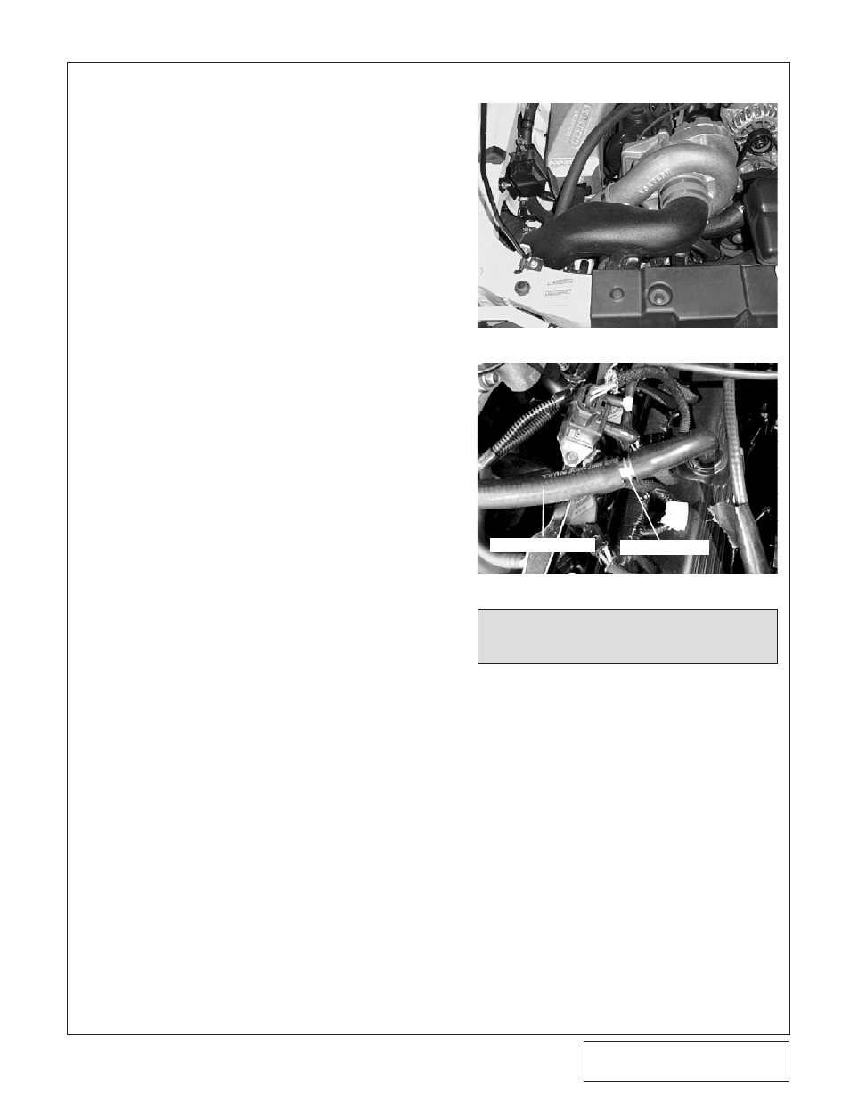
*O. Install the 5/8" hose union into the
crankcase breather line. It may be necessary
to trim this line to ensure a proper fit. (See
Fig. 10-c.)
P.
The plastic radiator cover removed in Step
1C must be modified to clear the air inlet
duct (1996-1997 only). Install the cover in its
original position and mark it as to where
material needs to be removed for duct
clearance. Using a razor blade or utility
knife, cut out the radiator cover to fit the
inlet ducting. Reinstall the cover and
re-secure.
* '99-'04 GT models only
** '01 Bullitt Model Only
*** '96-'04 GT Models Only
Fig. 10-b
Fig. 10-c / '99-'03 Models Only
10. AIR INLET, CONT’D.
5/8" BREATHER
5/8" HOSE
P/N: 4FL020-010
©2008 Vortech Engineering, LLC
All Rights Reserved, Intl. Copr. Secured
14APR08 v3.0 MusGT Bull(4FLv3.0)
21