Saf-te board with dcultra160-9kit configuration – StorCase Technology DS550 User Manual
Page 11
D89-0000-0187 Rev. A04
StorCase Technology, Inc.
S30A110
11
SAF-TE Board with DCULTRA160-9KIT Configuration
NOTES:
The optional DCULTRA160-9KIT is available as an upgrade (your particular
DS550 may or may not already be equipped with DCULTRA160-9KIT). Contact
StorCase for further ordering information.
Refer to the DCULTRA160-9KIT documentation for further information.
1.
Connect one end of the I/O Cable (provided) to the black I/O connector located on
top of the SAF-TE Board; connect the remaining end of the I/O Cable to the
DCULTRA160-9KIT Repeater Board (not included) as shown in Figure 8. Make sure
to fold the cable as shown in Figure 8 for proper fit.
2.
Connect one end of the I
2
C Cable (provided) to the I
2
C connector located on the
SAF-TE Board (Figure 6); connect the remaining end of the I
2
C Cable to the I
2
C
Connector (JB1) located on the DS550 Power Strip (Figure 8).
3.
Connect one split end of the DC Power Cable (provided) to the DC Power Connector
located on the SAF-TE Board (Figure 8); connect the other split end of the DC Power
Cable to the DCULTRA160-9KIT DC Power Cable (provided with the
DCULTRA160-9KIT). Connect the remaining end of the DC Power Cable to the
DS550 Power Strip (Figure 7).
4.
Connect the DS550 internal I/O cable to the silver I/O Connector located at the end
of the SAF-TE Board (Figure 9).
5.
If necessary, use the provided tie wraps to tie down any loose cables inside the
DS550 chassis.
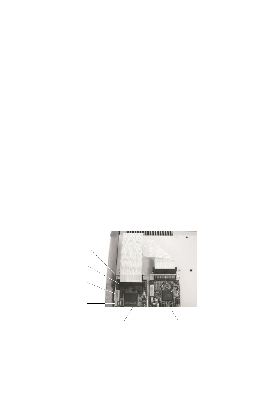
SAF-TE Processor
Board
Optional DCULTRA160-9KIT
Repeater Board
(Not Included)
I/O
Connector
(To SCSI Bus)
550_31
I/O
Connector
DC Power
Connector
I C
Connector
2
DC Power
Connector
I/O
Cable
Figure 8: Installing the I/O Cable
(DCULTRA160-9KIT Configuration)