StorCase Technology S20A120 User Manual
Page 18
S20A120 User's Guide - Rev. A01
StorCase Technology, Inc.
Installation
11
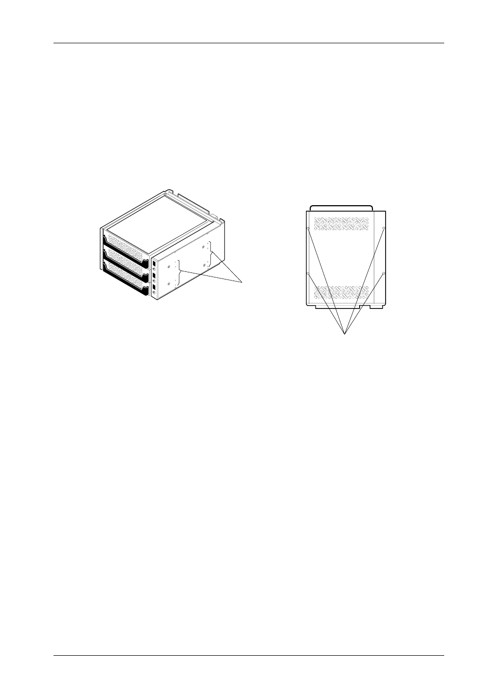
Mounting
Holes
(Right)
0520
Mounting
Holes
(Bottom)
Front of Unit
Figure 8: Receiving Frame Mounting Holes
5. Adjust the front of the receiving frame so the carrier slides freely in and out on the
receiving frame guides. The position of adjoining peripheral units may require
adjustment.
6. To connect a drive to a remote activity LED in the computer system or expansion chassis,
connect the appropriate cable(s) to the receiving frame motherboard connectors J3A1,
J3B1, and J3C1 Pins 11 & 12 as shown in Figure 5.
7. Connect the I/O cable from the host adapter to the receiving frame. The Pin 1 indicator
on the cable must be properly aligned. Refer to Figure 5 for the correct Pin 1 location.
NOTE:
No onboard termination is provided on the DE300. External termination
must be provided.
9. Connect the power cable from the DC power supply in the computer or expansion
chassis to the power connector on the DE300 receiving frame. Refer to Figure 5 for
the DE300 receiving frame power connector location.
4. With the drive carriers locked into place inside the receiving frame, install the DE300
receiving frame into the drive opening in the computer or expansion chassis. Use the
appropriate guides to position the DE300, and fasten it into place with eight (8) #6-32
Phillips screws provided. Figure 8 illustrates the location of the mounting holes.
Mounting holes are provided on each side and the bottom of the receiving frame to
accommodate a variety of mounting configurations. Use the mounting holes which best
suit the computer or expansion chassis configuration.