Receiving frame rear panel – StorCase Technology S20A120 User Manual
Page 12
Introduction
5
S20A120 User's Guide - Rev. A01
StorCase Technology, Inc.
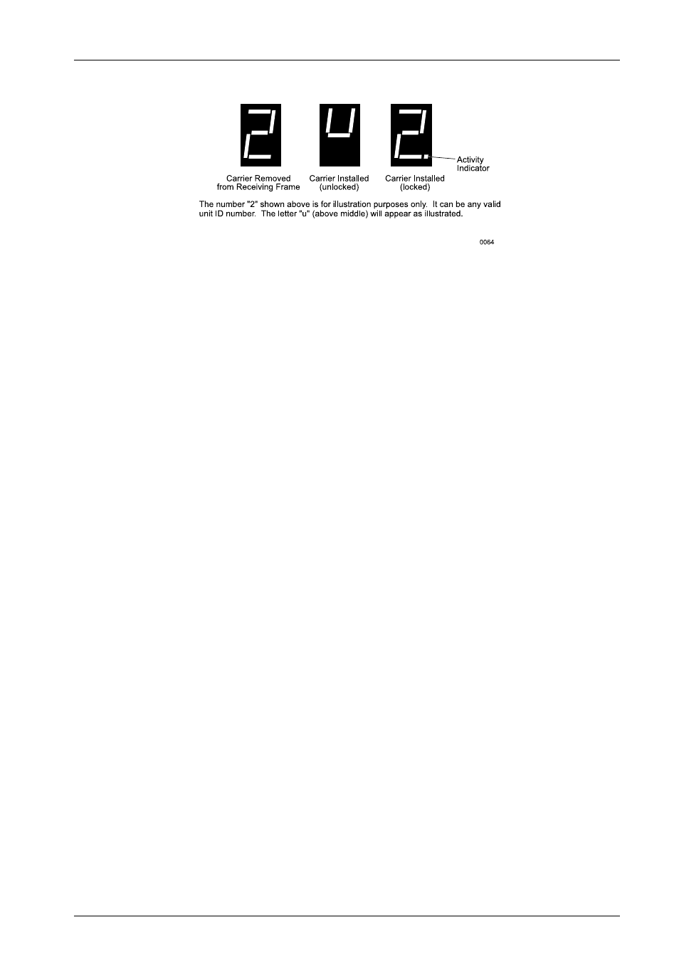
Figure 4: Receiving Frame Unit ID Number and Activity Display
Receiving Frame Rear Panel
(Figure 5)
I/O Connectors (J4, J6, and J8) - These connectors provide a standard interface for
all SCSI signals.
DC Power Connector - A standard 4-pin DC power connector is used to accept DC
power.
ID Select Connectors (J3A1, J3B1, and J3C1) - Pins 1-8 of these connectors provide
unit SCSI ID selection for the computer system or expansion chassis. For remote ID
selection through an expansion chassis, an appropriate cable must be attached to these
pins and the unit ID must be set to "0". The unit ID can be set with a rotating switch located
inside the receiving frame (Figure 9).
Remote Activity LED (RLED) - These pins provide power for a remote LED device
activity indicator (Pin 11=Cathode, Pin 12=Anode).
Jumpers - These jumpers were installed at the factory. Do not remove!
- DE100i-SW (35 pages)
- DE110 (27 pages)
- DE50 (33 pages)
- DE50 (27 pages)
- DE110 (33 pages)
- DE110 (2 pages)
- DE110 (31 pages)
- DX115 (25 pages)
- DE75i-A (31 pages)
- DE75i-A66 (29 pages)
- DE75i-A100 (31 pages)
- SATA DE75 (28 pages)
- DE75i-S (31 pages)
- DE75i-SW (33 pages)
- DE75i-SWC (33 pages)
- DE75i-SW160 (29 pages)
- S20A114 (29 pages)
- DE75i-SWC160 (29 pages)
- DE90i-A (29 pages)
- DE90i-A66 (23 pages)
- DE90i-A100 (23 pages)
- DE90i-S (25 pages)
- DE100i-A (33 pages)
- DE100i-A66 (29 pages)
- DE100i-A100 (29 pages)
- DE100i-CSWTN (2 pages)
- DE100i-S (39 pages)
- DE100i-SWD (33 pages)
- DE100i-SWU2 (37 pages)
- DE100i-SWCU2 (33 pages)
- DE100i-SWU2X (35 pages)
- DE100i-SW160 (35 pages)
- S20A102 (33 pages)
- DE100i-SWC160 (39 pages)
- Ultra320 DE100 (31 pages)
- DE110 (29 pages)
- DE110 (27 pages)
- DE110 (31 pages)
- DE150i-SWC (33 pages)
- DE200i-S (33 pages)
- DE200i-CSWTN (2 pages)
- DE200i-SW (35 pages)
- DE200i-SWU2 (37 pages)
- DE200i-SWCU2 (35 pages)
- S20A108 (33 pages)