Receiving frame rear panel – StorCase Technology DE75i-A66 User Manual
Page 12
DE75i-A66 User's Guide - Rev. A00
StorCase Technology Inc.
Introduction
5
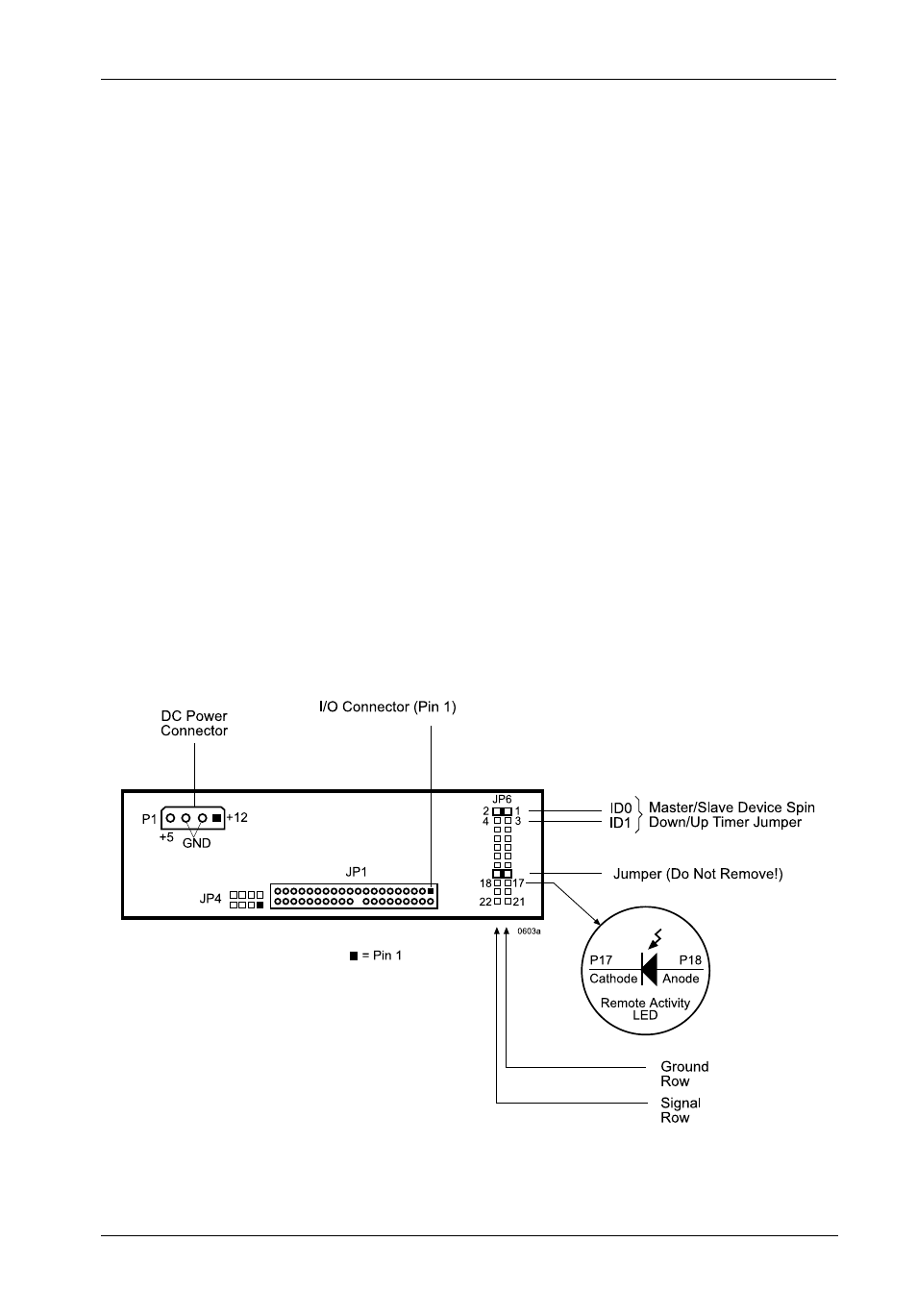
Figure 4: Receiving Frame Rear Panel (Motherboard)
Receiving Frame Rear Panel
(Figure 4)
DC Power Connector (P1): The Data Express uses a standard 4-pin DC
Power Connector to accept DC power.
I/O Connector (JP6): The input/output connector provides a standard
interface for all IDE signals. See Table 3 for JP1 pin assignments.
Master/Slave Selection (JP4): Master/Slave Drive configuration. Refer to the
"Installation" section for more specific information.
Option Pins (JP6)
Device Spin Down/Up Timer Jumper (ID0 & ID1): Jumper installed on Pins 1
and 2 (Factory Default) enables device spin down/up visual indicator for the
Master drive. Jumper installed on Pins 3 and 4 enables device spin down/up
visual indicator for the Slave drive.
Remote Drive Activity (JP6 RLED): Pins 17 and 18 are used for remote drive
activity.
Jumper (JP6 DDA): Installed at the factory - Do not remove!