Set jumper in high/low option position) – Star Headlight & Lantern STAR-PA RSK996P User Manual
Page 8
-6-
All Heads On and Off Together
(With High/Low Power Switching Option)
1. Use Star Model #SP3860-2H-OP switch panel (not included), or any other standard two-
switch switch panel capable of delivering 15 amps.
2. Connect the black wire from the POWER connector to a good chassis ground.
3. Connect the black and red ENABLE plug wires and the red POWER plug wire to +12VDC
through the first On/Off switch.
4. The white wire from the ENABLE plug allows utilization of the High//Low (Day/Night
Mode) option. The white wire from your ENABLE plug should be connected to the second
switch. When the white wire is connected to power through your second switch, the
pack will run in high power mode. When the second switch is in the “off” position, your
pack will operate in “Night Mode” (low power).
5.
The white wire from the POWER connector will be left unconnected for now. Once your
system is installed, the white wire will be used to program the flash pattern. Proceed to
the Pattern Selection section on page 8.
2-Head/4-Head Separate Activation (High Power Only)
(diagram on next page)
1. For this set up only two On/Off switches are necessary (not included). Use Star Model
#SP3860-2 switch panel, or any other standard two-switch switch panel capable of
delivering 15 amps.
2. Connect the black wire from the POWER connector to a good chassis ground.
3. Connect the red wire from the ENABLE plug to +12VDC through your first switch.
4. Connect the black wire from the ENABLE plug to +12VDC through your second switch.
5. Connect the red wire from the POWER plug and the white wire from the ENABLE plug
to +12VDC through a 15 amp fuse (not included).
Please Note: When the red POWER wire is connected to +12VDC the pack will draw a
small current (50 mA). If your vehicle will be sitting for extended periods of time (i.e.
more than a few days), it is recommended that all +12VDC wires be routed through an
ignition switched power source.
6.
The white wire from the POWER connector w ill be left unconnected for now. Once your
system is installed, the white wire will be used to program the flash pattern. Proceed to
the Pattern Selection section on page 8.
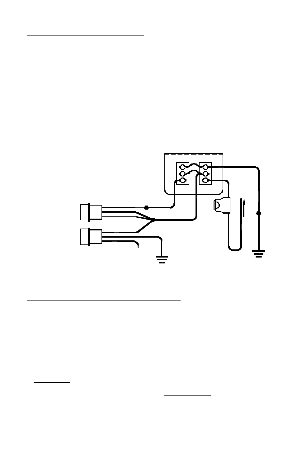
RP966/RP996
All Heads Activate Together
With High/Low Option
(Set Jumper in High/Low Option Position)
RED
PLUGS
INTO
POWER
PAK
ENABLE
CONNECTOR
WHITE
BLACK
PLUGS
INTO
POWER
PAK
POWER
CONNECTOR
WHITE
RED
BLACK
Pattern Select:
Touch and release to +12VDC
to set pattern then tape off
1
1
SW1
OFF
LOW
SW2
RED
GOOD
CHASSIS
GROUND
BLACK
SP3860-2H-OP LIGHTED SWITCH PANEL
(REAR VIEW)
O N
HIGH
2
3
2
3
BLUE
GOOD
CHASSIS
GROUND
CONNECT TO +12 VDC
15 AMP
FUSE