Troubleshooting – Spectrum Controls 1746sc-INI4vi User Manual
Page 50
46
SLC 500
™
Isolated Analog Input Modules
Troubleshooting
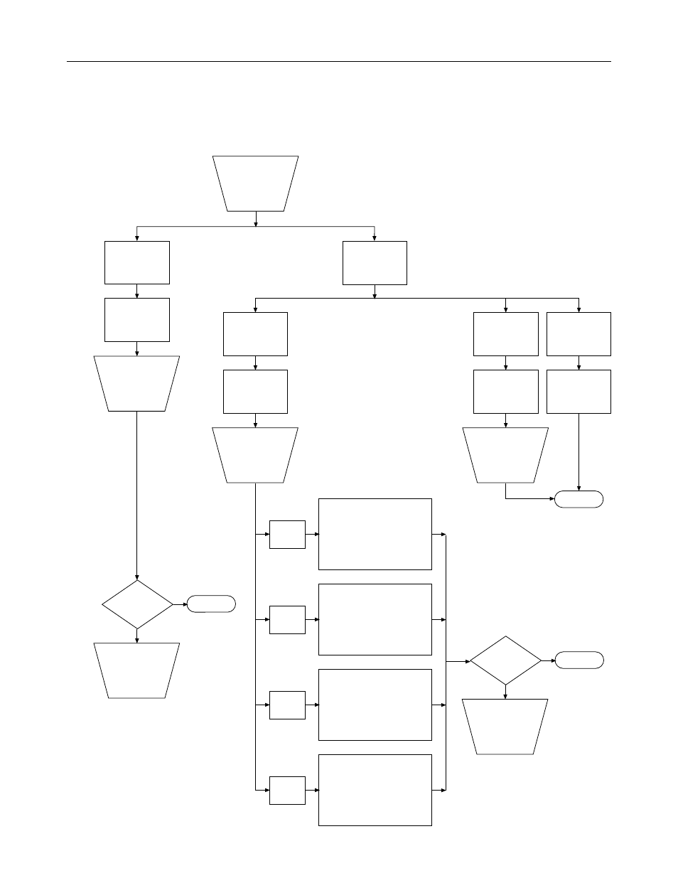
Figure 18. Problem resolution flowchart
Module
Status LED(s)
off.
Module fault
condition.
Check to see
that module is
seated properly
in chassis.
Cycle power.
Is problem
corrected?
Contact you local
distributor or
Spectrum
Controls.
Yes
No
End
Module
Status LED
on.
Check LEDs
on module.
Channel
Status LED(s)
blinking.
Channel
Status LED(s)
off.
Channel
Status LED(s)
on.
Channel is
not enabled.
Channel is
enabled and
working.
Enable channel if
desired by setting
channel config.
word (bit 0 = 1).
Retry.
End
Fault
condition.
Check channel
status word
bits 12–15.
Fatal channel error, such as
a software power-up failure
due to corrupt hardware or
malfunctioning software. Try
resetting the processor or
cycling power to your module.
Bit 15
set (1)
Non-fatal channel error, such
as an invalid configuration
word. Check the configuration
word. Correct and Retry.
Bit 14
set (1)
Low-range error. The input
signal is very near or below
the minimum limit for the
channel. Correct and Retry.
Bit 13
set (1)
High-range error. The input
signal is very near or above
the maximum limit for the
channel. Correct and Retry.
Bit 12
set (1)
Is problem
corrected?
Contact you local
distributor or
Spectrum
Controls.
No
Yes
End