Spectrum Controls 1746sc-INI4vi User Manual
Page 44
40
SLC 500
™
Isolated Analog Input Modules
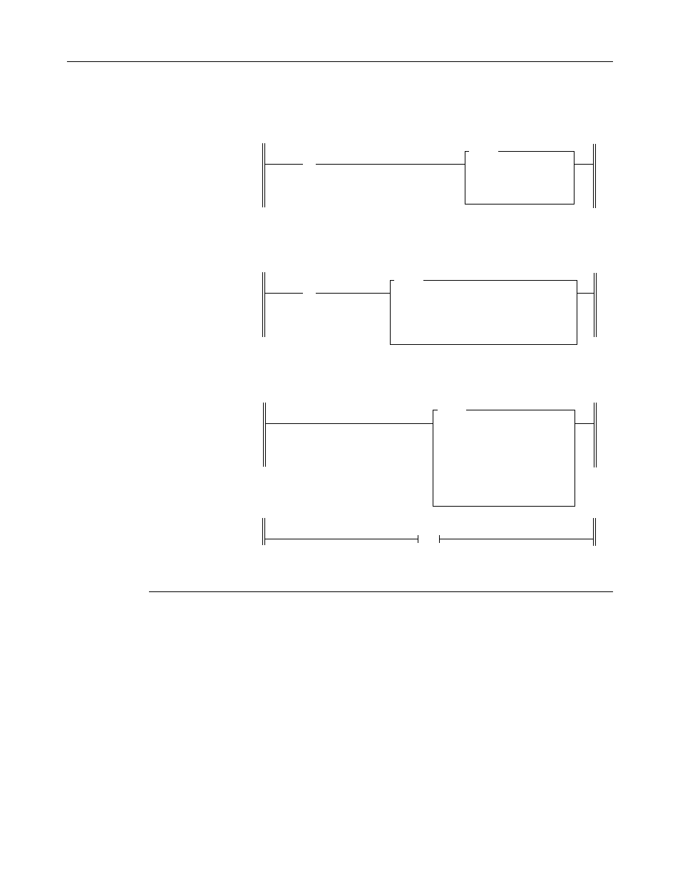
Figure 12. Programming for PID control example.
Rung 2:1
Channel 0 Status
I:3.4
] [
0
PID
PID
Control Block N11:0
Process Variable I:3.0
Control Variable N11:23
Control Block Length 23
Allocate N11:0 to N11: 22 for required Control Block file length of
23 words. The Process Variable is at I:3.0, which stores the value
of input data word 0 (channel 0). The output of the PID instruction
is at N11:23 (Control Variable address).
Rung 2:0
First Pass Bit
s:1
] [
15
MOV
MOVE
Source N10:0
Dest O:3.0
Initialize Module
Rung 2:2
SCL
SCALE
Source N11:23
Rate [/10000]
Offset
Dest
Set the Rate and Offset parameters for your application. The
Destination is typically an analog output channel. Refer to the
APS
User Manual or Analog I/O Modules User Manual for specific examples
of the SLC instruction.
END
Rung 2:3
Figure 13. Data table for PID control example.
address 15 data 0 address 15 data 0
N10:0 0000 0000 0001 1011
Important — When using your module’s Scaled For PID data format
with the SLC PID function, ensure that the Maximum Scaled S
max
(word7)
and Minimum Scaled S
min
(word 8) PID instruction parameters match
your module’s maximum and minimum scaled range in engineering units
for that channel. This allows you to accurately enter the setpoint in
engineering units.