Spectrum Controls 1746sc-INI4vi User Manual
Page 19
Chapter 2: Installing And Wiring Your Module
15
2. At each end of the cable, strip some casing to expose the individual
wires.
3. Trim the exposed signal wires to 2 in. lengths. Strip about 3/16 in.
(about 5 mm) of insulation away to expose the end of each wire.
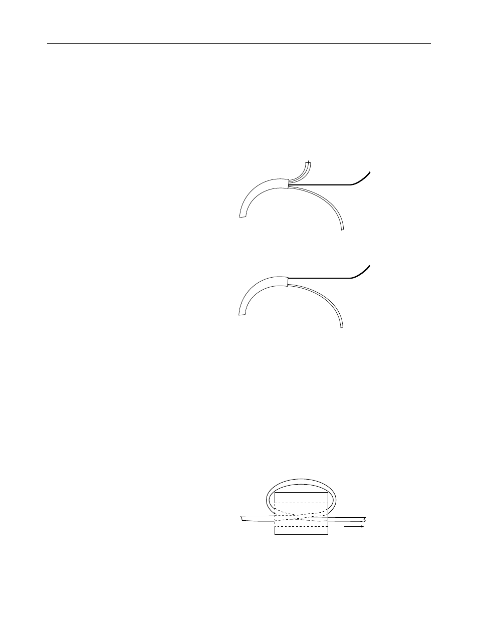
4. At one end of the cable, twist the drain wire and foil shield together,
bend them away from the cable, and apply shrink wrap.
Insulation
Clear Wire
Black Wire
Foil Shield and Drain Wire
5. At the other end of the cable, cut the drain wire and foil shield back to
the cable and apply shrink wrap.
Insulation
Clear Wire
Black Wire
6. Connect the wires to the terminal block and field device as shown in
the following figures and table. The recommended maximum torque is
5 in-lb (0.565 Nm) for all terminal screws.
To guard against electrostatic damage and improve chassis grounding,
connect one of the shield pins on the terminal block of your module to
the chassis itself
Important: For CE compliance, Ferrite EMI Suppressors are needed
on each channel’s terminal block connection. Apply the suppressor
close to the module terminal block, as shown below. A Steward Part
28B2024-0A0 or equivalent is recommended. The Steward 28B2024-
0A0 has an impedance of 157
Ω
at 25 MHz, 256
Ω
at 100 MHz, and
can accommodate one turn of wire.
Module