Spectrum Controls 1746sc-INI4vi User Manual
Page 39
Chapter 4: Using Your Input Module 35
In the preceding example...
S
low
= 3.5 U
low
= 100
S
high
= 20.5 U
high
= 9999
∆
S = 17
∆
U = 9899
Monitoring Each Input
Channel
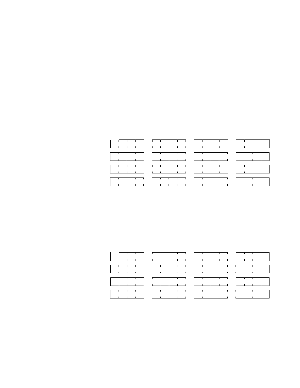
The input signal data resides in words 0 through 3 of the input image file
(addresses I:e.0 through I:e.3). The values present depend on the input
types and data formats selected. When an input channel is disabled, its
data word is set to zero.
Channel 0 Data Word
15
0
I:e.0
Address
Channel 1 Data Word
I:e.1
Channel 2 Data Word
I:e.2
Channel 3 Data Word
I:e.3
Checking Each Input
Channel’s Configuration
And Status
Words 4 through 7 of the input image file (addresses I:e.4 through I:e.7)
reflect the configuration and status of each channel. Use the data
provided in these status words to determine if the configuration data for
any channel is valid.
Channel 0 Status Word
15
0
I:e.4
Address
Channel 1 Status Word
I:e.5
Channel 2 Status Word
I:e.6
Channel 3 Status Word
I:e.7
Whenever a channel is disabled, its status word is set to zero. This
condition tells you that input data in the data word for that channel is not
valid and should be ignored.
A detailed explanation appears in Table 15.