Spectrum Controls 1746sc-INI4vi User Manual
Page 24
20
SLC 500
™
Isolated Analog Input Modules
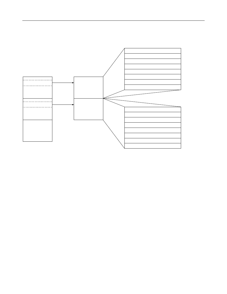
Figure 4. Image table for your isolated analog input module
Output Image
Slot e
Input Image
Slot e
SLC 5/0X
Data Files
Word 0
O:e.0
Word 1
O:e.1
Word 2
O:e.2
Word 3
O:e.3
Bit 15
Bit 0
Address
Channel 0 Configuration Word
Channel 1 Configuration Word
Channel 2 Configuration Word
Channel 3 Configuration Word
Word 4
O:e.4
Word 5
O:e.5
Word 6
O:e.6
Word 7
O:e.7
Low Limit of User-Defined Scale A
High Limit of User-Defined Scale A
Low Limit of User-Defined Scale B
High Limit of User-Defined Scale B
Output Image
8 Words
Analog Input Module
Image Table
Word 0
I:e.0
Word 1
I:e.1
Word 2
I:e.2
Word 3
I:e.3
Bit 15
Bit 0
Address
Channel 0 Data Word
Channel 1 Data Word
Channel 2 Data Word
Channel 3 Data Word
Word 4
I:e.4
Word 5
I:e.5
Word 6
I:e.6
Word 7
I:e.7
Channel 0 Status Word
Channel 1 Status Word
Channel 2 Status Word
Channel 3 Status Word
Input Image
8 Words
(Class 1)
Output
Scan
Input
Scan
Example – If you want to reconfigure channel 2 on your input module,
and it is in slot 4 of the SLC chassis, you would modify the configuration
word at address O:4.2. Alternatively, if you want to obtain the status of
channel 2, you would check the status word at address I:4.6.
The output and input image are described below.
Output Image—Configuration & User-Defined Scale Limits
The 8-word, output image (defined as the output from the SLC processor
to your module) defines how each channel on your module works:
• The configuration words replace configuration DIP switches on your
module. Each word configures a single channel.
• The user-defined scale limits define how your module scales analog
input values to a binary input register value, if one of the user-defined
scale data formats is selected.
Input Image—Data And Status Words
The 8-word, input image (defined as the input from your module to the
SLC processor) holds the data received by your module and provides the
status (configuration and operational state) of each channel.